
TM 5-3805-296-23-5
0333
DISASSEMBLY
000333
CAUTION
Plug and cap all air hoses and fittings to prevent contamination. Failure to follow this
caution may result in equipment failure.
NOTE
Tag and mark all hoses and fittings to aid in installation.
Note position of fittings to aid in installation.
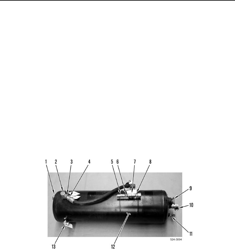
1. Using assistance, remove pipe plug (Figure 6, Item 1) from air tank (Figure 5, Item 12).
2. Loosen tube nut (Figure 6, Item 3) and remove air hose (Figure 6, Item 4) from fitting (Figure 6, Item 2).
3. Remove fitting (Figure 6, Item 2) from air tank (Figure 6, Item 12).
4. Remove air relief valve (Figure 6, Item 5) from fitting (Figure 6, Item 6).
5. Remove fitting (Figure 6, Item 6) from fitting (Figure 6, Item 7).
6. Remove fitting (Figure 6, Item 8) from fitting (Figure 6, Item 7).
7. Remove fitting (Figure 6, Item 7) from air tank (Figure 6, Item 12).
8. Using assistance, remove pipe plug (Figure 6, Item 9) from air tank (Figure 5, Item 12).
9. Remove fitting (Figure 6, Item 10) from air tank (Figure 6, Item 12).
10. Remove fitting (Figure 6, Item 11) from air tank (Figure 6, Item 12).
11. Remove fitting (Figure 6, Item 13) from air tank (Figure 6, Item 12).
Figure 6. Front Air Tank.
0333