
TM 5-3805-296-23-5
0319
INSTALLATION
000319
NOTE
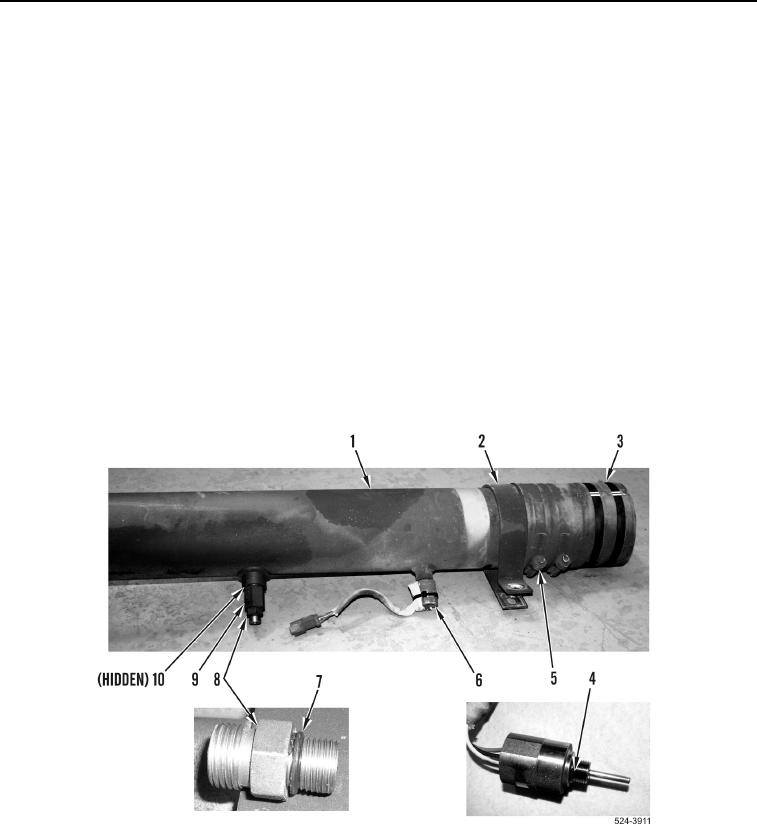
Install clamp as noted during removal.
1. Install clamp (Figure 13, Item 2) on hydraulic tank outlet tube (Figure 13, Item 1).
NOTE
Install clamps as noted during removal.
2. Install hose (Figure 13, Item 3) and two tighten two clamps (Figure 13, Item 5) on hydraulic tank outlet tube
(Figure 13, Item 1).
3. Install new o-ring (Figure 13, item 4) and hydraulic fluid temperature sensor (Figure 13, Item 6) on hydraulic
tank outlet tube (Figure 13, Item 1).
4. Install new O-ring (Figure 13, item 10) on fitting (Figure 13, item 9).
5. Install fitting (Figure 13, item 9) on hydraulic tank outlet tube (Figure 13, item 1).
6. Install new o-ring (Figure 13, Item 7) and fitting (Figure 13, Item 8) on hydraulic tank outlet tube
(Figure 13, Item 1).
Figure 13. Hydraulic Oil Temperature Sensor.
0319