
TM 5-3805-296-23-5
0319
INSTALLATION CONTINUED
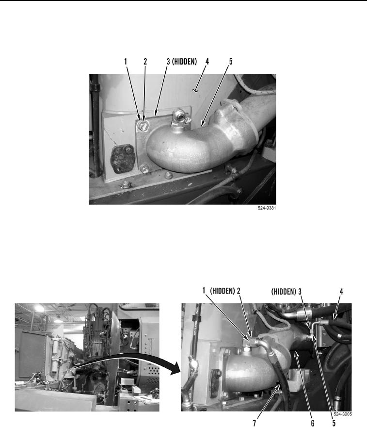
16. Install new O-ring (Figure 18, Item 3), elbow (Figure 18, Item 5), four washers (Figure 18, Item 1) and bolts
(Figure 18, Item 2) on hydraulic oil tank (Figure 18, Item 4).
Figure 18. Hose and Elbow.
0319
17. Install new O-ring (Figure 19, Item 3), hose (Figure 19, Item 4) and tighten tube nut (Figure 19, Item 5) on
hydraulic tank outlet tube (Figure 19, Item 6).
18. Install new O-ring (Figure 19, Item 2), hose (Figure 19, Item 7) and tighten tube nut (Figure 19, Item 1) on
hydraulic tank outlet tube (Figure 19, Item 6).
Figure 19. Hoses.
0319