
TM 5-3805-296-23-5
0319
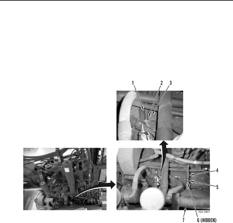
REMOVAL CONTINUED
12. Loosen tube nut (Figure 8, Item 5) and remove hose (Figure 8, Item 4) and O-ring (Figure 8, Item 6) from
hydraulic tank outlet tube (Figure 8, Item 7). Discard O-ring.
13. Remove hydraulic oil temperature sensor connector (Figure 8, Item 2) from bracket (Figure 8, Item 3).
NOTE
Tag and mark wiring harness connectors to aid in installation.
14. Disconnect hydraulic oil temperature sensor connector (Figure 8, Item 2) from wiring harness connector
(Figure 8, Item 1).
Figure 8. Hydraulic Oil Temperature Sensor.
0319