
TM 5-3805-296-23-5
0314
INSTALLATION CONTINUED
NOTE
Route wiring harness as noted during removal.
Install wiring harness connector as noted during removal.
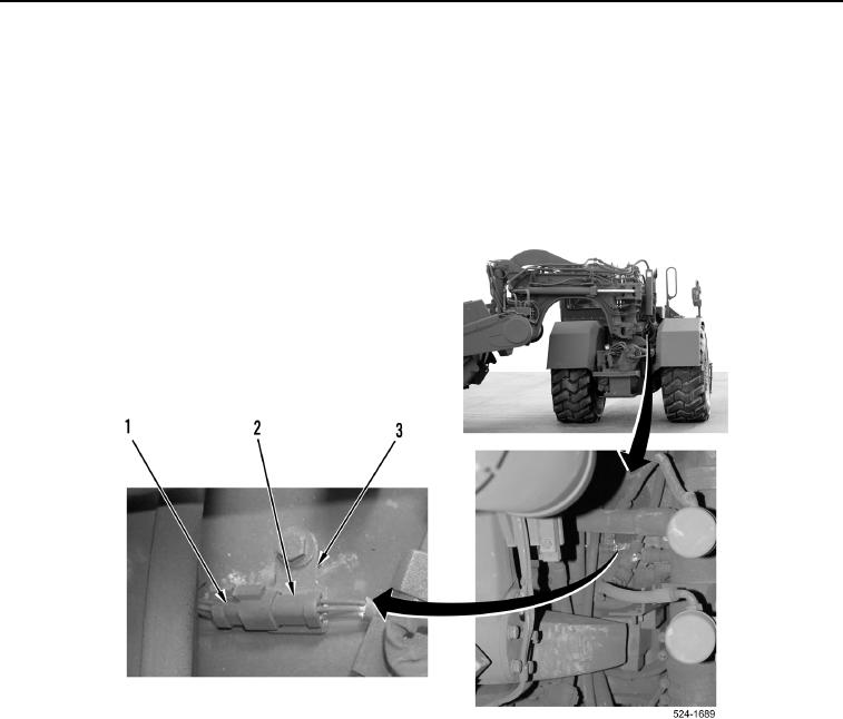
3. Install hydraulic temp sensor connector (Figure 6, Item 2) on bracket (Figure 6, Item 3).
4. Connect cushion hitch wiring harness connector (Figure 6, Item 1) to hydraulic temp sensor connector
(Figure 6, Item 1).
Figure 6. Wiring Harness Connector and Bracket.
0314