
TM 5-3805-296-23-4
0276
INSTALLATION CONTINUED
WARNING
Use extreme caution when handling heavy parts. Provide adequate support and use
assistance during procedure. Ensure any lifting device used is in good condition and of
suitable load capacity. Keep clear of heavy parts supported only by lifting device. Failure
to follow this warning may result in injury or death to personnel.
NOTE
Transmission and differential assembly weigh approximately 3,500 lb (1,588 kg).
It may be necessary to lower powertrain assembly on jack stand and use sling behind
steering cylinder to install powertrain assembly completely on machine.
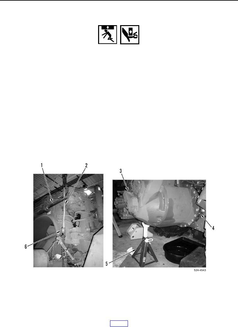
30. With assistance, using lifting device install transmission and differential assembly (Figure 38, Item 3) on
machine.
31. Lower transmission and differential assembly (Figure 38, Item 3) on trestle jack (Figure 38, Item 5) when lifting
device is against steering cylinder (Figure 38, Item 1).
32. Route nylon sling (Figure 38, Item 2) behind steering cylinder (Figure 38, Item 1) and attach to lifting chains
(Figure 38, Item 6).
33. Install transmission and differential assembly (Figure 38, Item 3) completely on machine studs
(Figure 38, Item 4).
Figure 38. Transmission Installation.
0276