
TM 5-3805-296-23-4
0276
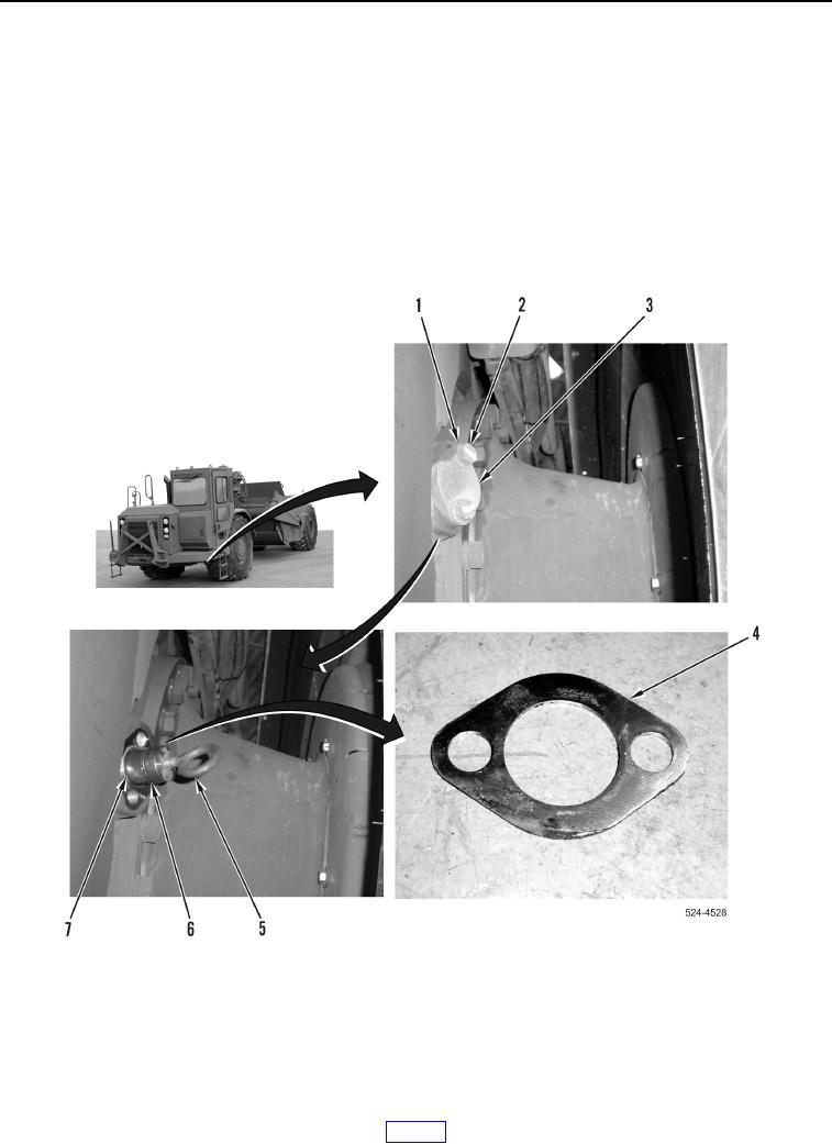
INSTALLATION CONTINUED
38. Install new O-ring (Figure 41, Item 6) on pin (Figure 41, Item 7).
39. Position pin (Figure 41, Item 7) on machine.
40. Install eye bolt (Figure 41, Item 5) on pin (Figure 41, Item 7).
41. Install pin (Figure 41, Item 7) on machine.
42. Remove eye bolt (Figure 41, Item 5).
43. Do not install shim pack (Figure 41, Item 4) at this time.
44. Install cap (Figure 41, Item 3), two washers (Figure 41, Item 1), and bolts (Figure 41, Item 2).
45. Tighten bolts (Figure 41, Item 2) evenly with hand wrench.
Figure 41. Differential Support Pin.
0276