
TM 5-3805-296-23-4
0276
INSTALLATION CONTINUED
WARNING
Use extreme caution when handling heavy parts. Provide adequate support and use
assistance during procedure. Failure to follow this warning may result in injury or death to
personnel.
CAUTION
Transmission output shaft splines must align with differential input splines for proper
installation. Failure to follow this caution may result in damage to equipment.
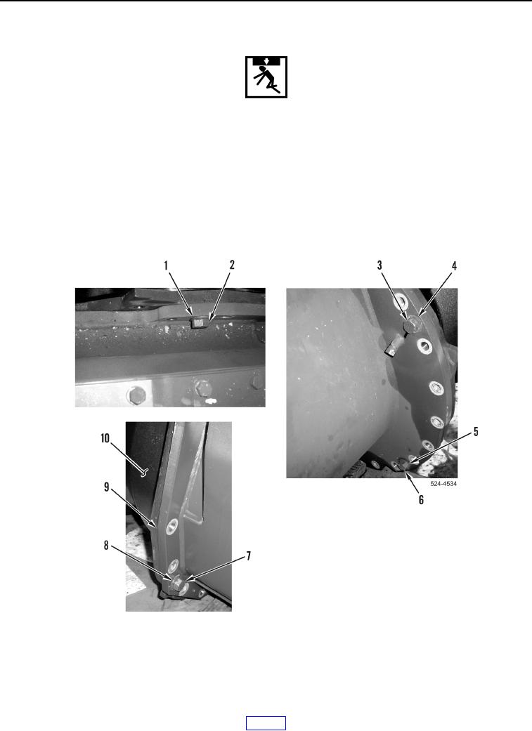
21. With assistance, using lifting device install differential (Figure 34, Item 10) on transmission (Figure 34, Item 9).
22. Install four washers (Figure 34, Items 1, 4, 5, and 8) and bolts (Figure 34, Items 2, 3, 6, and 7).
Figure 34. Transmission Flange.
0276