
TM 5-3805-296-23-4
0276
REMOVAL CONTINUED
NOTE
Tag and mark wiring harness connections to aid in installation.
Note location and quantity of tiedown straps to aid in installation.
Note routing of wiring harness to aid in installation.
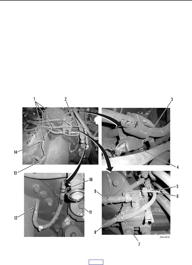
30. Remove three tiedown straps (Figure 10, Item 1) from ladder clips (Figure 10, Item 14).
31. Disconnect secondary steering wiring harness connector (Figure 10, Item 13) and remove secondary steering
wiring harness (Figure 10, Item 2) from machine.
32. Loosen tube nuts (Figure 10, Items 10 and 12) and remove differential lock air hose (Figure 10, Item 11) from
machine.
33. Disconnect cushion hitch wiring harness (Figure 10, Item 3) from transmission wiring harness connector
(Figure 10, Item 4).
34. Remove tiedown strap (Figure 10, Item 5) from ladder clip (Figure 10, Item 6).
35. Remove bolt (Figure 10, Item 9), washer (Figure 10, Item 8), and P-clamp (Figure 10, Item 7) from machine.
36. Slide transmission wiring harness connector (Figure 10, Item 4) forward and remove from bracket.
Figure 10. Right Side of Transmission.
0276