
TM 5-3805-296-23-4
0276
REMOVAL CONTINUED
NOTE
Note location of tiedown strap to aid in installation.
Tag and mark wiring harness connectors to aid in installation.
Note routing of wiring harness to aid in installation.
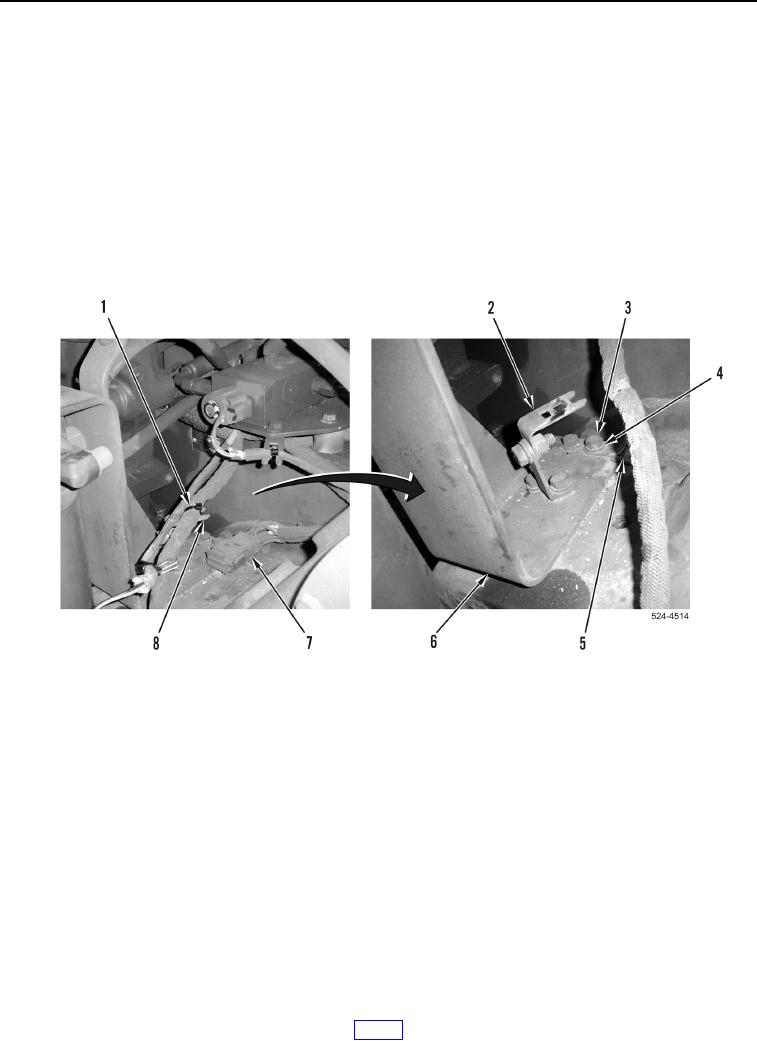
11. Slide connector (Figure 5, Item 7) forward and remove from bracket (Figure 5, Item 5).
12. Remove tiedown strap (Figure 5, Item 1) from ladder clip (Figure 5, Item 8).
13. Remove four bolts (Figure 5, Item 3), washers (Figure 5, Item 4), harness bracket (Figure 5, Item 5), and
ladder clip bracket (Figure 5, Item 2) from hydraulic filter bracket (Figure 5, Item 6).
14. Remove hydraulic filter bracket (Figure 5, Item 6) from machine.
Figure 5. Rear of Transmission.
0276