
TM 5-3805-296-23-4
0275
BRAKE DRUM REMOVAL
000275
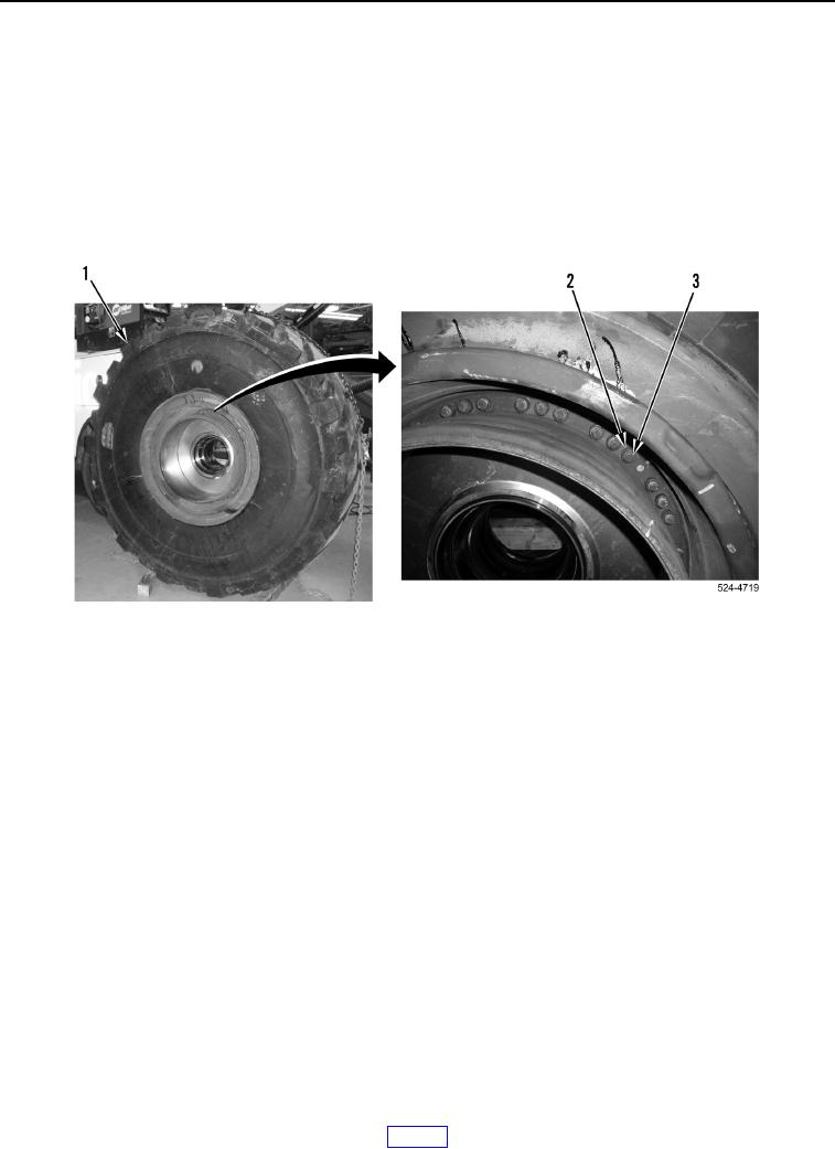
1. Modify two 1/2 x 13 x 6 machine bolts to make brake drum alignment pins (WP 0541).
NOTE
Remove two bolts from opposite sides of brake drum. Alignment pins will be installed in
bolts holes to support brake drum during removal.
2. Remove two bolts (Figure 9, Item 3) and spacer (Figure 9, Item 2) from wheel assembly (Figure 9, Item 1).
Discard bolts.
Figure 9. Bolts.
0275