
TM 5-3805-296-23-4
0251
REMOVAL CONTINUED
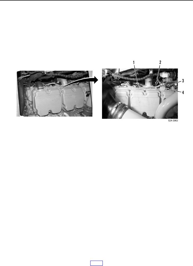
6. Disconnect basic engine wiring harness connector (Figure 5, Item 3) from injector wiring harness connector
(Figure 5, Item 4).
NOTE
Note quantity and location of tiedown straps to aid in installation.
7. Remove tiedown straps (Figure 5, Item 2) from basic engine wiring harness (Figure 5, Item 1). Discard tiedown
straps. Position basic engine wiring harness aside.
Figure 5. Injector Connector.
0251