• Home
  • Download PDF
  • Order CD-ROM
  • Order in Print
Figure 3. Basic Engine Wiring Harness.
Figure 5. Injector Connector.

Field Maintenance Manual For Military 621G Scraper -4 Page Navigation
  389    390    391    392    393  394  395    396    397    398    399  
img
.
TM 5-3805-296-23-4
0251
REMOVAL CONTINUED
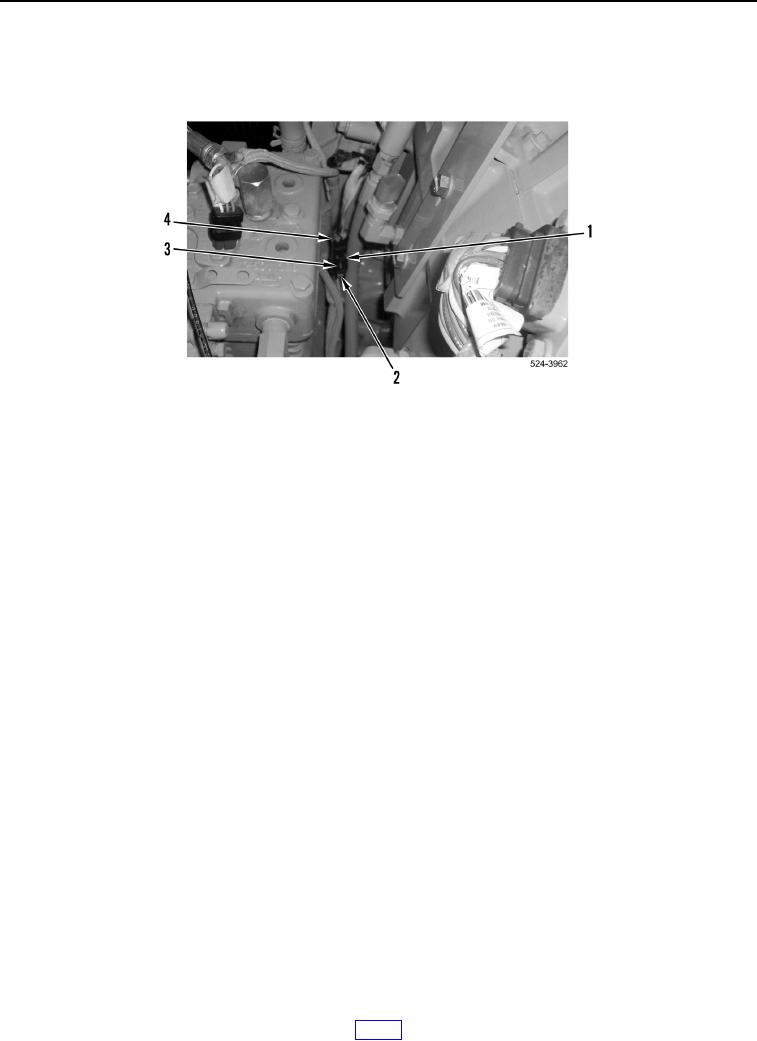
5. Slide lock tab (Figure 4, Item 2) to unlock position, press tab (Figure 4, Item 3), and disconnect basic engine
wiring harness connector (Figure 4, Item 1) from camshaft speed timing sensor connector (Figure 4, Item 4).
Figure 4. Camshaft Speed Timing Sensor.
0251
0251-5


Privacy Statement
Press Release
Contact

© Copyright Integrated Publishing, Inc.. All Rights Reserved.