
TM 5-3805-296-23-4
0240
ENGINE OIL COOLER BYPASS INSTALLATION CONTINUED
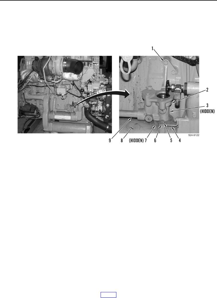
5. Install new O-ring (Figure 10, Item 7) and oil cooler bypass manifold on tube (Figure 10, Item 9) and oil cooler
(Figure 10, Item 8).
6. Install three bolts (Figure 10, Items 1 and 3) on oil cooler bypass manifold (Figure 10, Item 2).
7. Install bracket (Figure 10, Item 4), two washers (Figure 10, Item 6), and bolts (Figure 10, Item 5) on engine.
Figure 10. Oil Cooler Bypass.
0240