
TM 5-3805-296-23-2
0118
Table 1. Secondary Steering Indicator Always Illuminated Continued.
0118
MALFUNCTION
TEST OR INSPECTION
CORRECTIVE ACTION
4. Using digital multimeter
Secondary Steering
Resistance 5.0 Ohms or Less
(WP 0540), measure resistance
Indicator Always Illuminated
Proceed to step 5.
between connector W-C1
Continued
Resistance Greater Than 5.0 Ohms
terminal 69 (WP 0012, Figure 99)
Replace main cab wire harness
and ground.
(WP 0505).
Proceed to Test Step 9.
5. Using digital multimeter
Resistance 5.0 Ohms or Less
(WP 0540), measure resistance
Proceed to Test Step 8.
between connector W-C1
Resistance Greater Than 5.0 Ohms
terminal 54 (WP 0012, Figure 99)
Replace main cab wire harness
and connector W-C7 terminal 25
(WP 0505).
(WP 0012, Figure 252).
Proceed to Test Step 9.
Test Step 8. Test Dash Wiring
Harness for High Resistance or
Open.
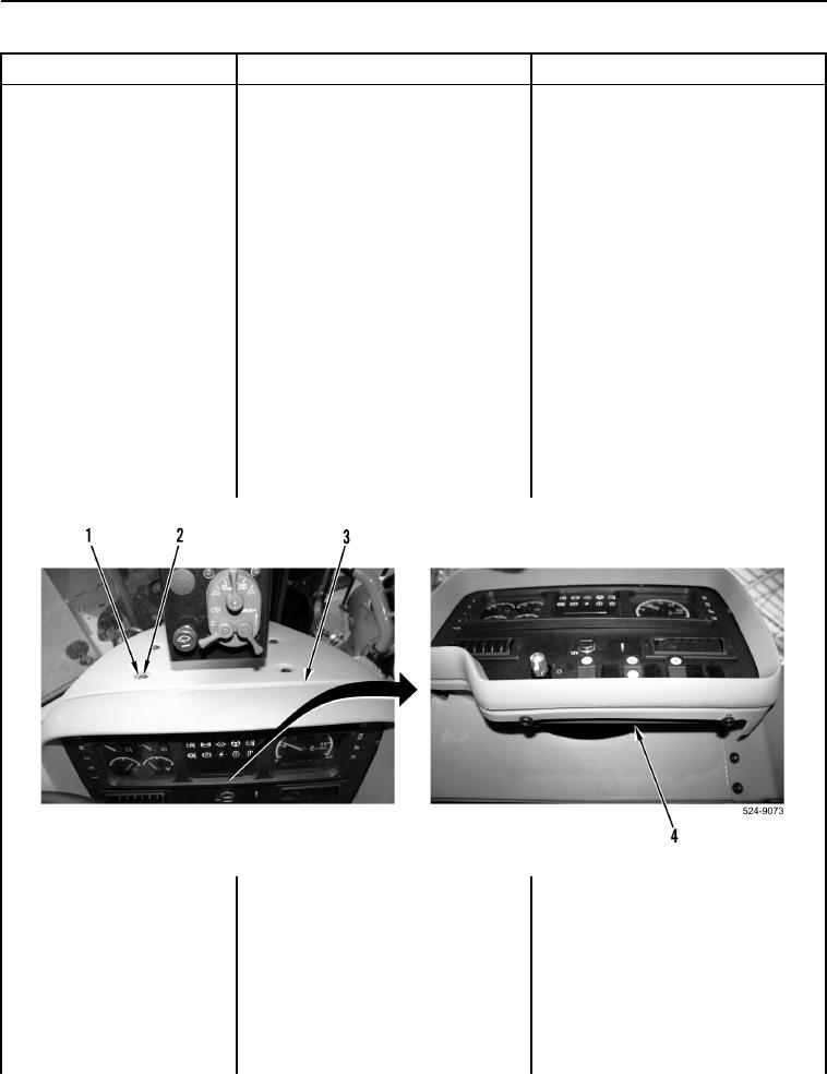
1. Remove six bolts (Figure 1,
Item 1), washers (Figure 1,
Item 2), and instrument panel
cover (Figure 1, Item 3) from
ROPS (Figure 1, Item 4).
Figure 1. Instrument Panel Cover and Retaining Hardware.
0118