
TM 5-3805-296-10
0002
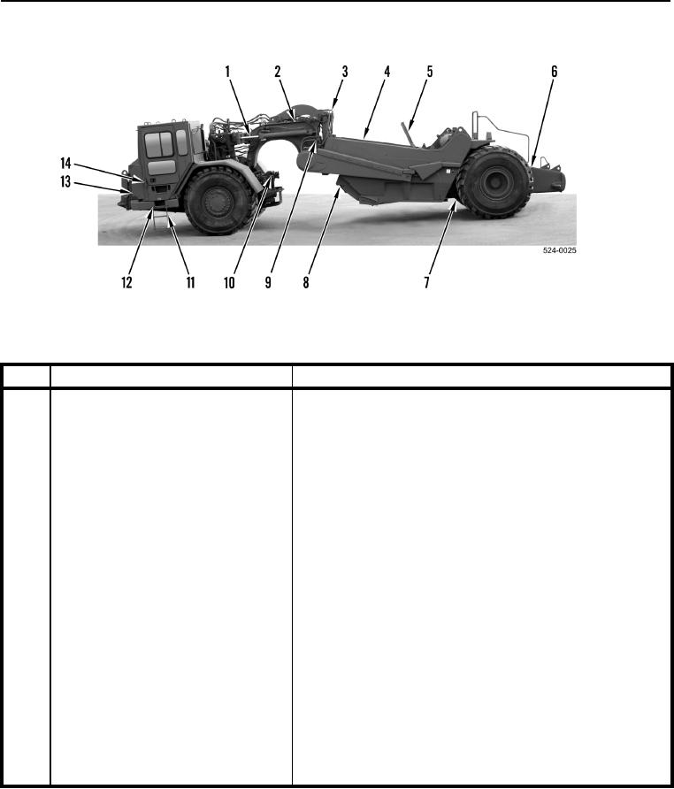
LOCATION AND DESCRIPTION OF MAJOR COMPONENTS
0002
Figure 1. Military 621G Scraper (Left Side).
0002
.
KEY
COMPONENT
DESCRIPTION
1
Steering Cylinders
Provides steering actuation. Location for steering cylinder lock
installation.
2
Apron Cylinder (located within
Provides open/close action for apron.
gooseneck)
3
Bowl Cylinders
Provides lift/lower action for bowl.
4
Bowl
Used to move and store material.
5
Ejector
Empties bowl of material.
6
Tool Box
Storage location for BII items.
7
Ejector Cylinder
Provides forward/rearward action for ejector.
8
Apron
Used to regulate distribution of material and seal front of bowl.
9
Bowl Flood Lamp
Provides illumination for scraper and bowl.
10
Cutting Edge Flood Lamp
Provides illumination for scraper and cutting edge.
11
Step
Provides safe means to climb on and off machine.
12
Tractor Air Tank Drain Valves
Bank of three valves provide means to drain water and air
from tractor air system.
13
Tractor Ground Level Shutdown
Provides external source to shut off electrical power to the
Switch
machine.
14
Access Door
Provides access to outer cab filter.