TM 5-3805-296-10
0002
LOCATION AND DESCRIPTION OF MAJOR COMPONENTS CONTINUED
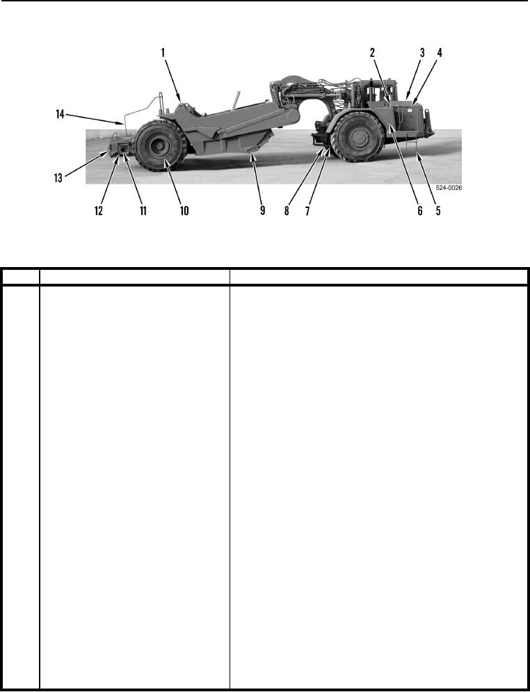
Figure 2. Military 621G Scraper (Right Side).
0002
KEY
COMPONENT
DESCRIPTION
1
Fuel Tank Filler Neck and Cap
Provides means to fill and seal fuel tank.
2
Hydraulic Oil Tank Filler Neck and
Provides means to fill and seal hydraulic oil tank.
Cap
3
Hood
Provides access to engine compartment.
4
Engine Access Doors
Provides access to engine compartment. The following fluid
levels can be checked: coolant, engine oil, window washer
fluid.
The following can also be accessed: engine air filter indicator,
fuel system primer switch, fuel system shutoff valve, fuel/water
separator, drive belts, NATO slave receptacle, battery
disconnect switch.
5
Step
Provides safe means to climb on and off machine.
6
Hydraulic Oil Tank Sight Gauge
Provides means to check hydraulic oil level.
7
Transmission Sight Gauge
Upper sight gauge provides means to check transmission oil
level. Oil is red in color.
8
Differential and Final Drive Oil Level
Lower sight gauge provides means to check differential and
Sight Gauge
final drive oil level. Oil is yellow in color.
9
Router Bits and Cutting Edges
Replaceable outer (router bits) and lower edges (cutting
edges) of bowl.
10
Tire Valve Stem
Provides means to check tire air pressure and fill as required.
11
Scraper Air Tank Drain and Fuel Tank
Provides means to drain water from scraper air system (valve
located to the front of opening).
Water and Sediment Drain
Provides means to drain water and sediment from fuel tank
(valve located to the rear of the opening).
12
Step
Provides safe means to climb on and off machine.
13
Push Block
Location where a push tractor contacts and assists machine.
14
Grab Handle
Provides safe hand hold for walking on rear of machine.

