TM 9-4940-568-20
11-48
Materials/Parts – Continued
Locknut (4) (Item 30, Appendix F)
Locknut (4) (Item 35, Appendix F)
Locknut (4) (Item 46, Appendix F)
Lockwasher (Item 74, Appendix F)
Ring, Snap (4) (Item 95, Appendix F)
This task covers:
a. Removal
b. Disassembly
c. Cleaning/Inspection
d. Assembly
e. Installation
f. Follow-On Maintenance
INITIAL SETUP
Equipment Condition
FRS unloaded, (TM 9-4940-568-10)
Air system drained, (TM 9-4940-568-10)
Tools and Special Tools
Tool Kit, General Mechanic’s: Automotive
(Item 30, Appendix G)
Socket Set, 3/8 in. (Item 25, Appendix G)
Wrench, Combination, 1-1/4 in.
(Item 36, Appendix G)
Wrench, Combination, 1-1/2 in.
(Item 39, Appendix G)
Wrench, Pipe 1 1/2 in. (Item 43, Appendix G)
11-13. PNEUMATIC HOSE REEL AND 3/4” HOSE REPAIR.
Materials/Parts
Cloth, Cleaning (Item 13, Appendix C)
Grease, Automotive and Artillery (GAA)
(Item 20, Appendix C)
Sealing Compound (Item 32, Appendix C)
Solvent, Drycleaning (Item 38, Appendix C)
Personnel Required
Two
a.
Removal.
1
3
4
2
Hose reel assembly is under pressure. Avoid releasing latching mechanism during
removal and installation. Failure to comply could result in injury to personnel.
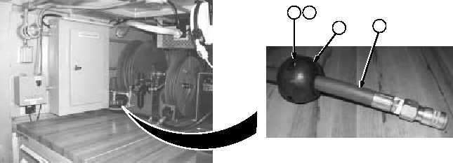
(1)
Remove two screws (1), nuts (2), and hose bumper assembly (3) from hose (4).