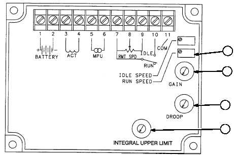
4
1
3
2
TM 9-4940-568-20
8-46
8-16. ENGINE ELECTRONIC OVERSPEED MODULE REPLACEMENT (CONT).
c.
Adjustment.
(1)
Electronic Overspeed Module Adjustments: If necessary, insure module is wired according to the
illustration and install the magnetic speed pickup sensor (Para 8-17). Then adjust the governor controller
as follows:
(a)
The potentiometers (pots) on the controller are adjustable from zero to 100 percent and are marked
off in divisions of ten percent. The speed pot has a 20-turn adjustment range. Set the pots initially
as follows:
GAIN (1) 30 %
INTEGRAL UPPER LIMIT (2) 0% (fully CCW)
DROOP 0% (3) (fully CCW)
(b)
If a remote speed pot is used, set it at its midpoint.
(c)
Start the set and adjust the RUN SPEED (4) pot to obtain the required output frequency: 60 Hertz
(1800 RPM) or 50 Hertz (1500 RPM). Warm up the set under load until it is up to normal operating
temperature.
(d)
Disconnect the load and turn the GAIN (1) pot to 100 percent or until operation becomes unstable.
Then turn the pot counterclockwise until operation again becomes stable.
(e)
Interrupt the governor by momentarily removing power from the governor. The engine should
recover in 3 to 5 diminishing speed oscillations.
(f)
If engine continues to hunt, slightly reduce GAIN (1) setting (turn pot counterclockwise). Repeat
Step (e).
(g)
After the RUN SPEED (4) and GAIN (1) are adjusted, apply 100% rated load to the generator.
(h)
Readjust RUN SPEED (4) if necessary.
d.
Follow-On Maintenance:
Connect batteries, (TM 9-4940-568-10).
Start generator and check for proper operation, (TM 9-4940-568-10).
Install rear panel, (TM 9-4940-568-10).
END OF TASK


