
TM 5-3805-296-23-6
0385
CLEANING AND INSPECTION
000385
Clean and inspect all components IAW Mechanical General Maintenance Instructions (WP 0539).
END OF TASK
ASSEMBLY
000385
NOTE
The following procedure is for assembly of the left side headlight. Use same procedure for
right side headlight assembly.
Install ladder bracket as noted during removal.
Route wiring harness as noted during removal.
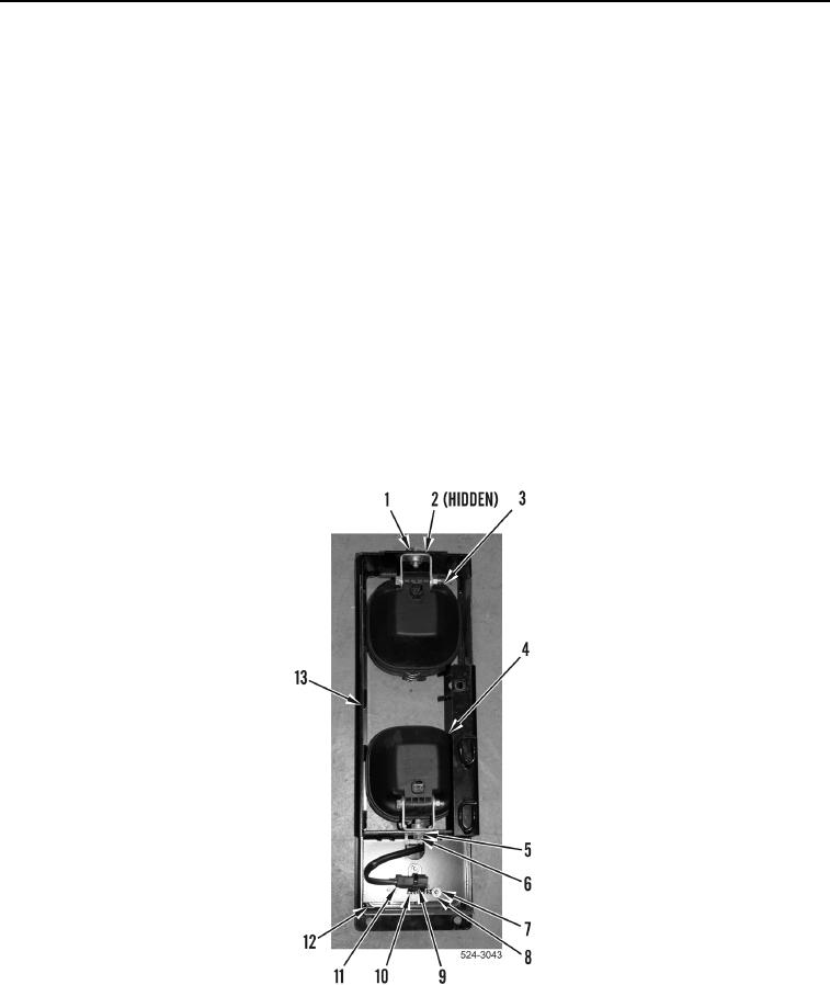
1. Install turn signal lamp (Figure 24, Item 12), ladder bracket (Figure 24, Item 10), three washers
(Figure 24, Item 8), and nuts (Figure 24, Item 7) on headlight assembly (Figure 24, Item 13).
2. Install new tiedown strap (Figure 24, Item 9) on turn signal lamp wiring harness connector (Figure 24, Item 11).
3. Install low beam headlight (Figure 24, Item 4), washer (Figure 24, Item 5), and bolt (Figure 24, Item 6) on
headlight assembly (Figure 24, Item 13).
4. Install high beam headlight (Figure 24, Item 3), washer (Figure 24, Item 2), and bolt (Figure 24, Item 1) on
headlight assembly (Figure 24, Item 13).
Figure 24. Headlight Assembly.
0385