
TM 5-3805-296-23-5
0354
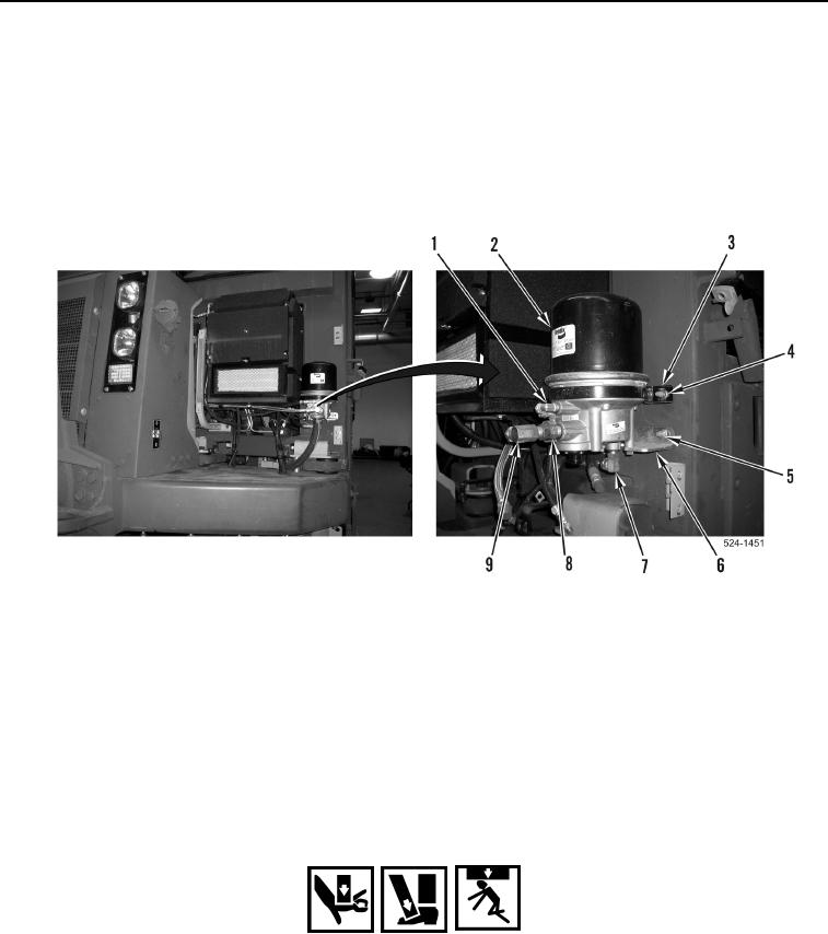
REMOVAL CONTINUED
7. Remove fitting (Figure 3, Item 1) from brake air dryer (Figure 3, Item 2).
8. Remove fitting (Figure 3, Item 7) from brake air dryer (Figure 3, Item 2).
9. Remove fitting (Figure 3, Item 9) from fitting (Figure 3, Item 8).
10. Remove fitting (Figure 3, Item 8) from brake air dryer (Figure 3, Item 2).
11. Remove two nuts (Figure 3, Item 5) from lower mounting bracket (Figure 3, Item 6).
12. Remove two nuts (Figure 3, Item 4) from upper mounting bracket (Figure 3, Item 3).
13. Remove brake air dryer (Figure 3, Item 2) from machine.
Figure 3. Mounting Bolts.
0354
END OF TASK
CLEANING AND INSPECTION
000354
1. Clean and inspect all components IAW Mechanical General Maintenance Instructions (WP 0539).
2. Clean and inspect all components IAW Electrical General Maintenance Instructions (WP 0540).
END OF TASK
INSTALLATION
000354
WARNING
Wheels must remain chocked during entire procedure. Failure to follow this warning may
result in injury or death to personnel.
1. Position brake air dryer (Figure 3, Item 2) on machine.
2. Install two nuts (Figure 3, Item 4) on upper mounting bracket (Figure 3, Item 3).
3. Install two nuts (Figure 3, Item 5) on lower mounting bracket (Figure 3, Item 6).