• Home
  • Download PDF
  • Order CD-ROM
  • Order in Print
Figure 3. Left Actuator Valve Connections.
Figure 5. Right Rear P-clamp and Grommet.

Field Maintenance Manual For Military 621G Scraper -5 Page Navigation
  734    735    736    737    738  739  740    741    742    743    744  
img
.
TM 5-3805-296-23-5
0342
REMOVAL CONTINUED
NOTE
Note location of P-clamps to aid in installation.
Note routing and location of air hoses to aid in installation.
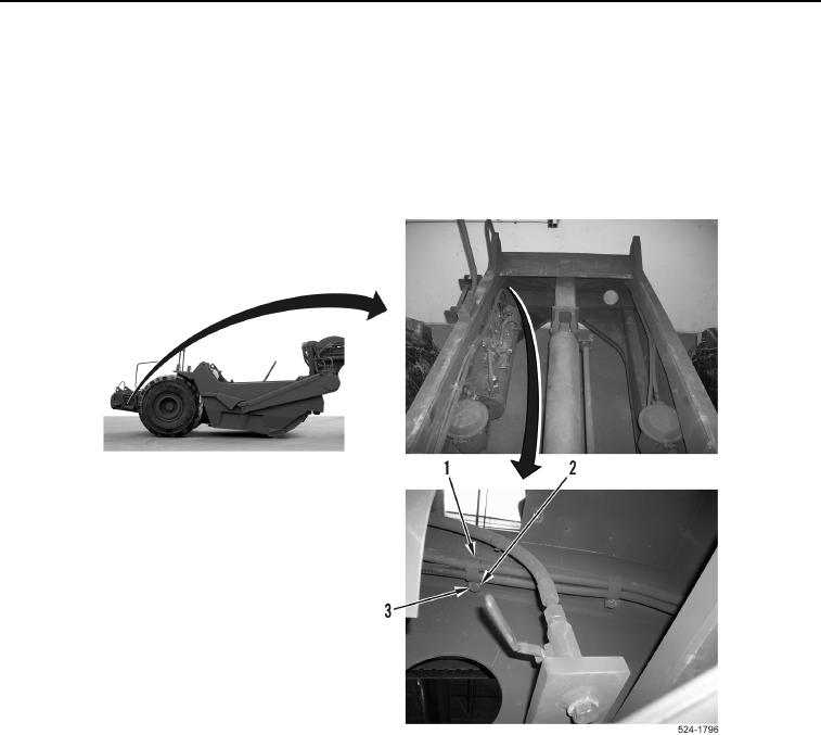
7. Remove two bolts (Figure 4, Item 3), washers (Figure 4, Item 2), and P-clamps (Figure 4, Item 1) from
machine.
Figure 4. Right Frame Rail P-clamps.
0342
0342-5


Privacy Statement
Press Release
Contact

© Copyright Integrated Publishing, Inc.. All Rights Reserved.