• Home
  • Download PDF
  • Order CD-ROM
  • Order in Print
Figure 15. Air Tank.
Figure 17. Air Hoses and Valves.

Field Maintenance Manual For Military 621G Scraper -5 Page Navigation
  621    622    623    624    625  626  627    628    629    630    631  
img
.
TM 5-3805-296-23-5
0337
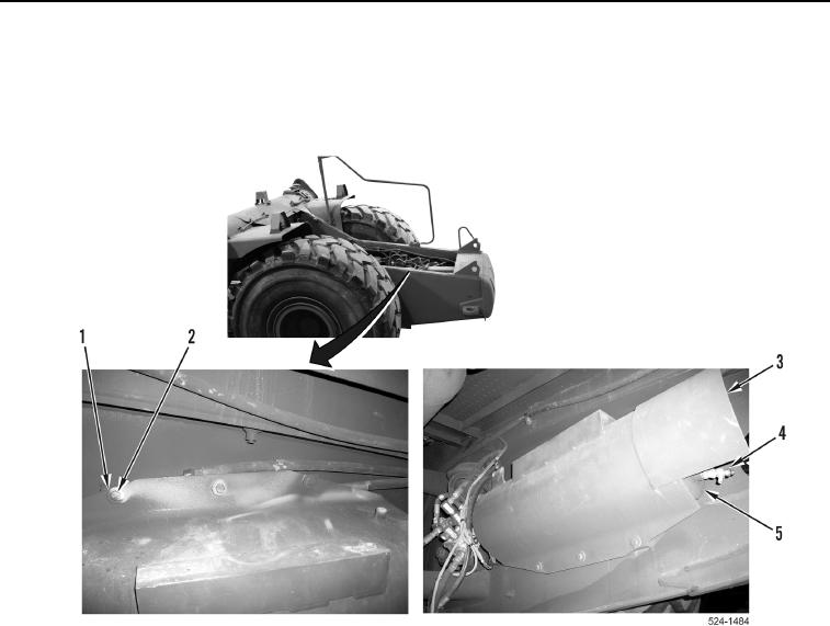
INSTALLATION CONTINUED
1. Air tank (Figure 16, Item 5) is mounted with drain valve (Figure 16, Item 4) at 6 O'clock position.
2. With assistance, install air tank (Figure 16, Item 5), air tank cover (Figure 16, Item 3), six washers (Figure 16,
Item 1), and bolts (Figure 16, Item 2) on machine.
Figure 16. Air Tank and Cover.
0337
0337-17


Privacy Statement
Press Release
Contact

© Copyright Integrated Publishing, Inc.. All Rights Reserved.