
TM 5-3805-296-23-4
0282
INSTALLATION CONTINUED
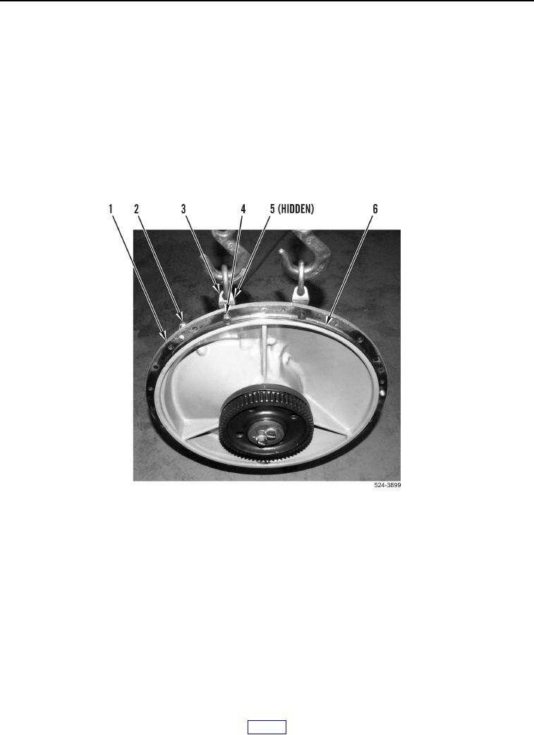
23. Install new O-ring (Figure 21, Item 6) on bearing housing (Figure 21, Item 1).
NOTE
Install bolts as noted during removal.
Install link bracket as noted during removal.
24. Install three forcing bolts (Figure 21, Item 2) in threaded holes on bearing housing (Figure 21, Item 1).
25. Install two link brackets (Figure 21, Item 3), bolts (Figure 21, Item 5), and nuts (Figure 21, Item 4) on bearing
housing (Figure 21, Item 1).
26. Install lifting device on link brackets (Figure 21, Item 3).
Figure 21. Bearing Housing O-ring.
0282