
TM 5-3805-296-23-4
0280
CONTROL VALVE PILOT HOSES REMOVAL CONTINUED
CAUTION
Plug and cap all hydraulic hoses lines, and fittings to prevent contamination. Failure to
follow this caution may result in damage to equipment.
NOTE
Tag and mark hydraulic hoses and lines to aid in installation.
Note routing and location of hydraulic hoses and lines to aid in installation.
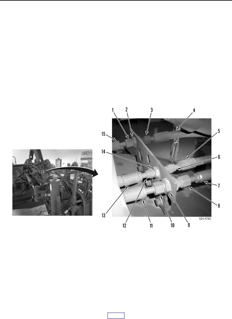
25. Loosen three tube nuts (Figure 8, Items 3, 6, and 8) and remove hoses (Figure 8, Items 4, 5, and 7) from
fittings (Figure 8, Items 2, 14, and 9).
26. Loosen three tube nuts (Figure 8, Items 1, 10, and 12) and remove hoses (Figure 8, Items 11, 13 and 15) from
fittings (Figure 8, Items 2, 14, and 9).
27. Remove three lines (Figure 8, Items 4, 5, and 7) from machine.
Figure 8. Middle Draft Frame Hydraulic Fittings.
0280