
TM 5-3805-296-23-4
0276
INSTALLATION CONTINUED
NOTE
Remove plugs and caps from hydraulic hoses and fittings.
Install hydraulic hoses as tagged and marked during removal.
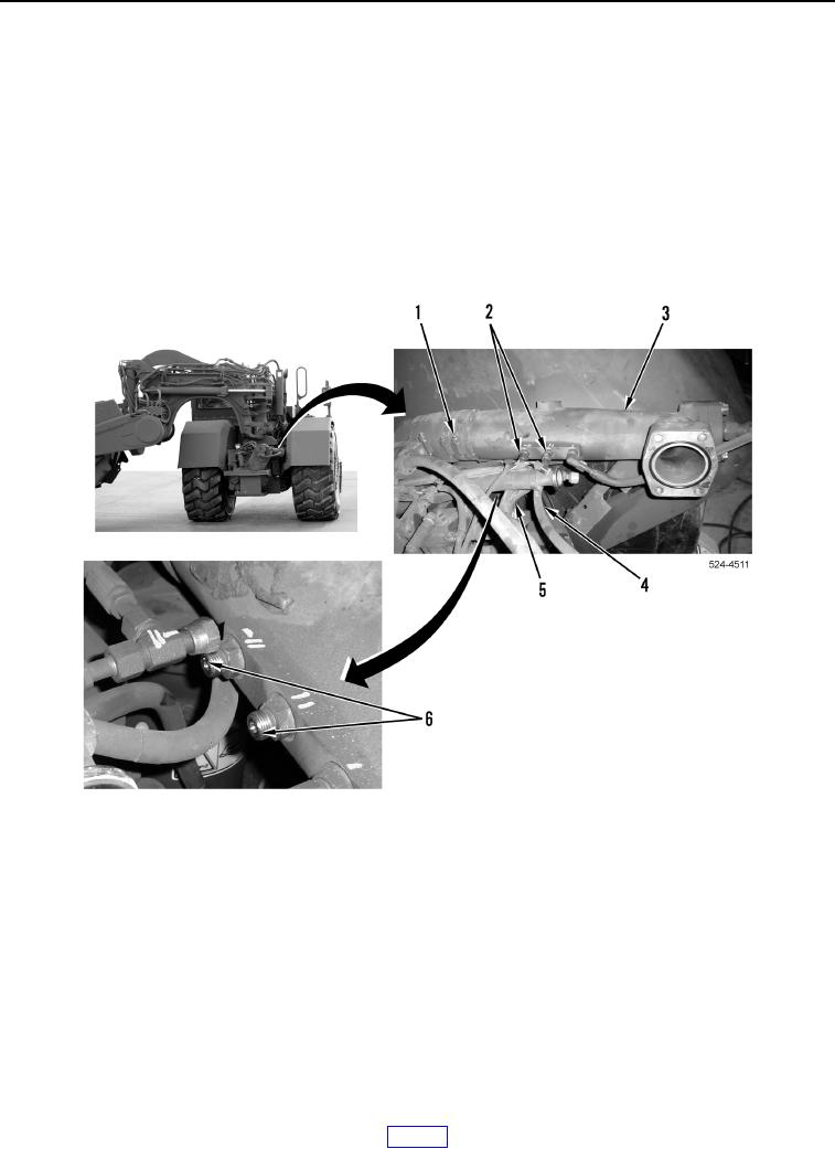
101. Install suction hose (Figure 58, Item 3) on machine.
102. Install two new O-rings (Figure 58, Item 6) on suction hose (Figure 58, Item 3).
103. Install two lines (Figure 58, Items 4 and 5) on suction hose (Figure 58, Item 3) and tighten tube nuts
(Figure 58, Item 2).
104. Tighten two clamps (Figure 58, Item 1) on suction hose (Figure 58, Item 3).
Figure 58. Suction Hose.
0276