
TM 5-3805-296-23-4
0272
REMOVAL CONTINUED
CAUTION
Plug and cap hoses and fittings to prevent contamination.
NOTE
Tag and mark hose and tube to aid in installation.
Note hose routing to aid in installation.
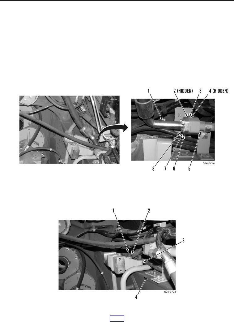
17. Remove four bolts (Figure 6, Item 8), washers (Figure 6, Item 7), two flange halves (Figure 6, Item 6), hose
(Figure 6, Item 1), O-ring (Figure 6, Item 2), spacer plate (Figure 6, Item 3), and O-ring (Figure 6, Item 4) from
line (Figure 6, Item 5). Discard O-rings.
Figure 6. Steering Return Hose.
0272
18. Using assistance, remove two bolts (Figure 7, Item 1), washers (Figure 7, Item 2), and engine mount bracket
(Figure 7, Item 3) from frame (Figure 7, Item 4).
Figure 7. Engine Mount Bracket.
0272