
TM 5-3805-296-23-4
0264
INSTALLATION CONTINUED
NOTE
Remove plugs and caps from hydraulic hoses and fittings.
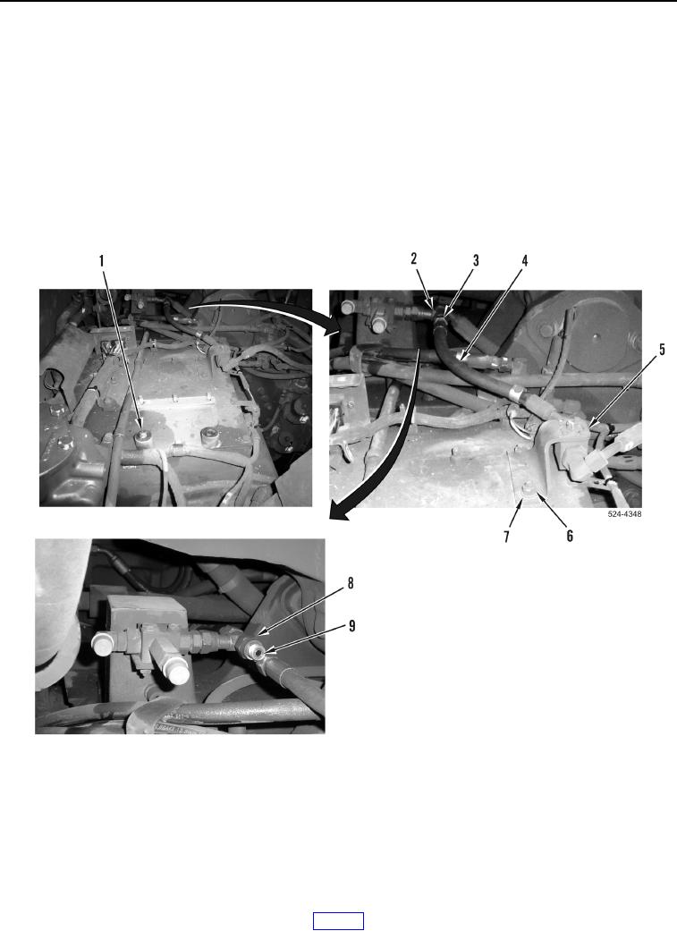
Install hydraulic hoses as tagged and marked during removal.
54. Route and install bracket (Figure 52, Item 5) and line (Figure 52, Item 4) on transmission.
55. Install two washers (Figure 52, Item 7), and nuts (Figure 52, Item 6) on bracket (Figure 52, Item 5).
56. Install new O-ring (Figure 52, Item 9) on fitting (Figure 52, Item 8).
57. Install line (Figure 52, Item 4) on fitting (Figure 52, Item 2) and tighten tube nut (Figure 52, Item 3).
58. Install two spacers (Figure 52, Item 1) on machine.
Figure 52. Top of Transmission.
0264