
TM 5-3805-296-23-4
0264
REMOVAL CONTINUED
NOTE
Cap and plug all lines and fittings to prevent fluid loss.
Note routing of hydraulic lines to aid in installation.
Mark and tag hydraulic lines to aid in installation.
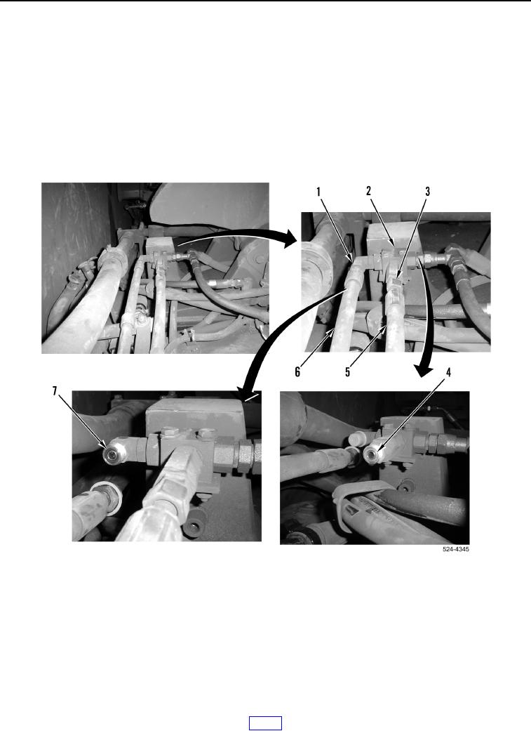
15. Loosen two tube nuts (Figure 6, Items 1 and 3) and remove two lines (Figure 6, Items 5 and 6) from fitting
(Figure 6, Item 2).
16. Remove two O-rings (Figure 6, Items 4 and 7) from fitting (Figure 6, Item 2). Discard O-rings.
Figure 6. Front of Transmission.
0264