
TM 5-3805-296-23-4
0232
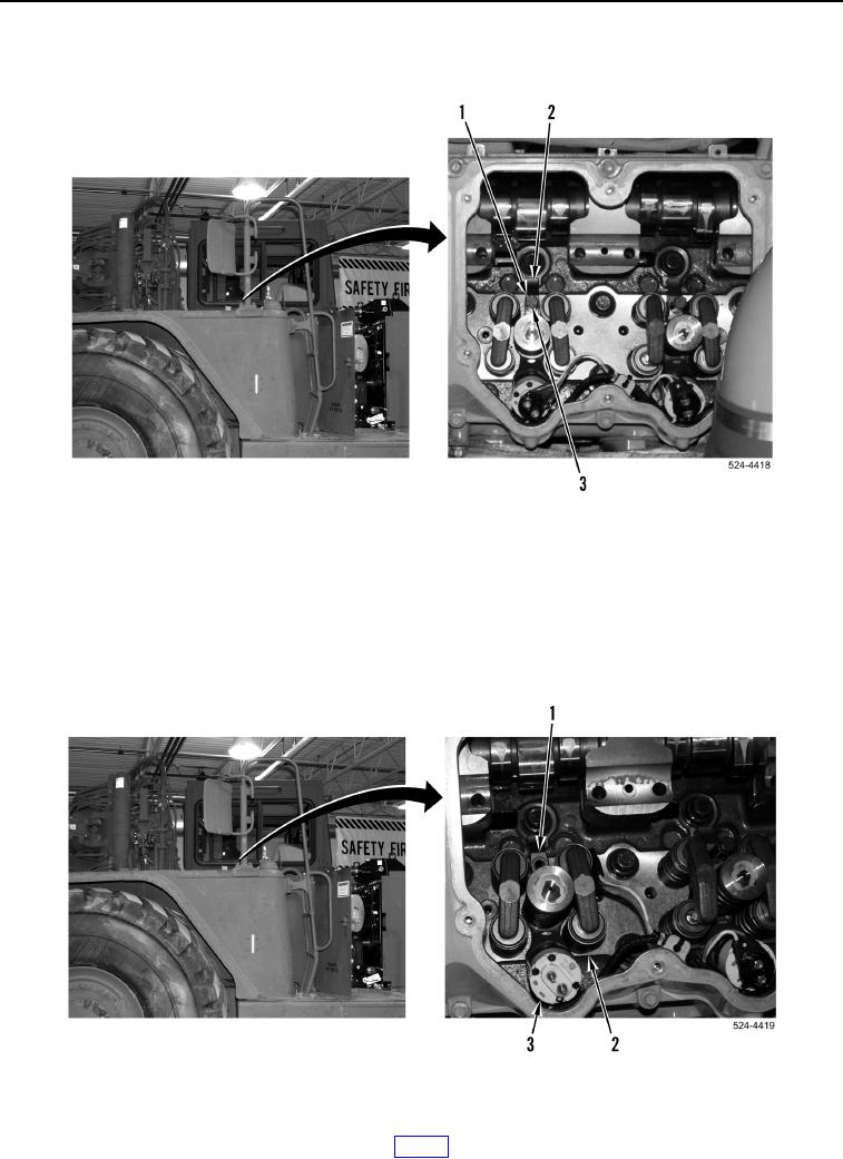
REMOVAL CONTINUED
4. Remove bolt (Figure 3, Item 3) and spacer (Figure 3, Item 1) from clamp (Figure 3, Item 2). Discard bolt.
Figure 3. Bolt and Spacer.
0232
NOTE
Tag and mark each fuel injector to aid in installation. Each fuel injector must be reinstalled
at original location on cylinder head.
5. Remove clamp (Figure 4, Item 1) and fuel injector (Figure 4, Item 3) from cylinder head (Figure 4, Item 2).
Figure 4. Clamp and Fuel Injector.
0232