
TM 5-3805-296-23-4
0231
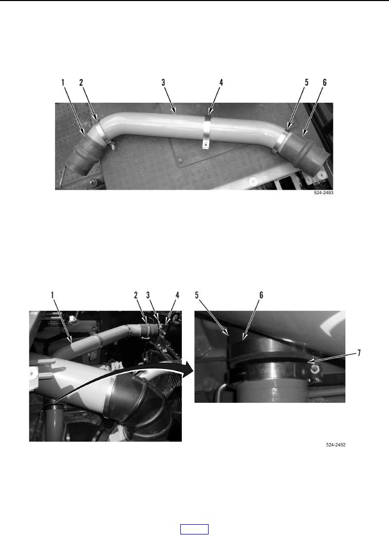
UPPER AIR LINE INSTALLATION CONTINUED
4. Position clamp (Figure 29, Item 4) on upper air line (Figure 29, Item 3).
5. Position clamp (Figure 29, Item 5) and hose (Figure 29, Item 6) on upper air line (Figure 29, Item 3).
6. Position clamp (Figure 29, Item 2) and hose (Figure 29, Item 1) on upper air line (Figure 29, Item 3).
Figure 29. Upper Air Line and Hoses.
0231
7. Position clamp (Figure 30, Item 3) on aftercooler (Figure 30, Item 4).
8. Position clamp (Figure 30, Item 6) on adapter (Figure 30, Item 7).
9. Install hose (Figure 30, Item 2) and upper air line (Figure 30, Item 1) on aftercooler (Figure 30, Item 4).
10. Install upper air line (Figure 30, Item 1) and hose (Figure 30, Item 5) on adapter (Figure 30, Item 7).
Figure 30. Upper Air Line and Aftercooler.
0231