
TM 5-3805-296-23-4
0228
FUEL RETURN LINE INSTALLATION CONTINUED
NOTE
Install P-clamps in locations noted during removal.
Route and install fuel hoses as noted during removal.
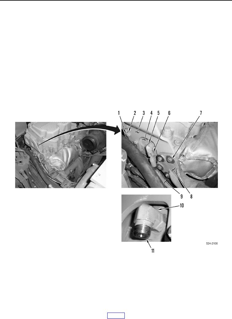
3. Position rear lift eye (Figure 15, Item 3) on cylinder head (Figure 15, Item 4).
4. Install four bolts (Figure 15, Item 1), washers (Figure 15, Item 2), and rear lift eye (Figure 15, Item 3) on
cylinder head (Figure 15, Item 8).
5. Position bracket (Figure 15, Item 8) on rear lift eye (Figure 15, Item 3).
6. Install four bolts (Figure 15, Item 7) and bracket (Figure 15, Item 8) on rear lift eye (Figure 15, Item 3).
7. Install new O-ring (Figure 15, Item 11) on fitting (Figure 15, Item 10).
8. Position cylinder head fuel return hose (Figure 15, Item 9) on machine.
9. Install cylinder head fuel return hose (Figure 15, Item 9) on fitting (Figure 15, Item 5) and tighten tube nut
(Figure 15, Item 6).
Figure 15. Cylinder Head Fuel Return Hose and Fitting.
0228