
TM 5-3805-296-23-4
0228
FUEL RETURN LINE REMOVAL CONTINUED
NOTE
Tag and mark fuel hoses to aid in installation.
Note location and orientation of P-clamps to aid in installation.
Note routing and location of fuel hoses to aid in installation.
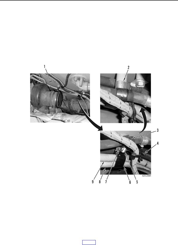
6. Remove bolt (Figure 12, Item 5), washer (Figure 12, Item 7), two P-clamps (Figure 12, Items 3 and 6), ladder
clip (Figure 12, Item 4), and spacer (Figure 12, Item 2) from hydraulic oil tank (Figure 12, Item 1).
7. Remove P-clamp (Figure 12, Item 6) from cylinder head fuel return hose (Figure 12, Item 9) and cylinder head
fuel supply hose (Figure 12, Item 8).
Figure 12. P-clamps and Ladder Clip.
0228