
TM 5-3805-296-23-2
0104
Table 1. Engine Will Not Crank Continued.
0104
MALFUNCTION
TEST OR INSPECTION
CORRECTIVE ACTION
Engine WIll Not Crank
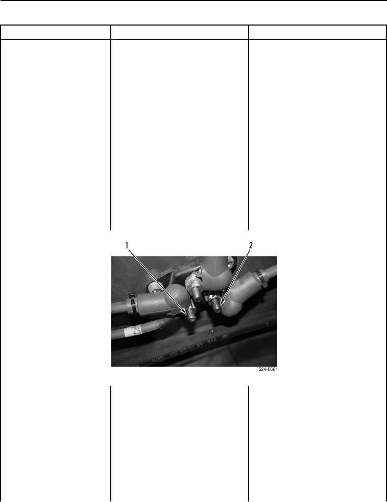
Test Step 20. Test Voltage to
Continued
Junction Block
1. Turn battery disconnect switch to
ON position (TM 5-3805-296-10).
Voltage Within One Volt of Battery
2. Using digital multimeter
Voltage (Previously Noted) Proceed
(WP 0540), test for voltage
to step 3.
between positive terminal
Voltage Not Within One Volt of
(Figure 15, Item 1) and ground.
Battery Voltage (Previously Noted)
Replace battery positive cable
(WP 0307).
Proceed to Test Step 27.
Voltage Within One Volt of Battery
3. Using digital multimeter
Voltage (Previously Noted) Position
(WP 0540), test for voltage
all boots on cables to cover terminals.
between positive terminal
Proceed to Test Step 21.
(Figure 15, Item 2) and ground.
Voltage Not Within One Volt of
Battery Voltage (Previously Noted)
Replace junction block (WP 0310).
Proceed to Test Step 27.
Figure 15. Testing Voltage to Junction Block.
0104