
TM 5-3805-296-23-2
0104
Table 1. Engine Will Not Crank Continued.
0104
MALFUNCTION
TEST OR INSPECTION
CORRECTIVE ACTION
Engine WIll Not Crank
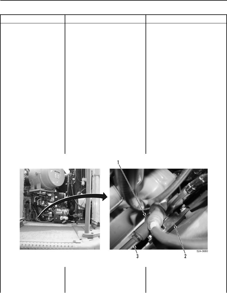
12. Position three boots aside
All Cables and Junction Block OK -
Continued
(Figure 14, Item 1) and inspect
Proceed to Test Step 20.
cables (Figure 14, Item 3) and
Cable(s) Damaged - Replace
junction block (Figure 14, Item 2)
damaged cable(s) (WP 0307)
for damage, and loose and
(WP 0310).
corroded connections (WP 0540).
Proceed to Test Step 27.
Junction Block Damaged - Replace
junction block (WP 0310).
Proceed to Test Step 27.
Cable Connection(s) Corroded
Disconnect battery positive cable from
battery (WP 0307).
Clean (WP 0540) and connect cable(s)
to junction block (WP 0310).
Connect battery positive cable to
battery (WP 0307).
Proceed to Test Step 27.
Cable Connection(s) Loose
Disconnect battery positive cable from
battery (WP 0307).
Tighten cable connection(s).
Connect battery positive cable to
battery (WP 0307).
Proceed to Test Step 27.
Figure 14. Battery and Starter Positive Cables at Junction Block.
0104