
TM 3-4240-302-30&P-6
2-7. AIRFLOW VALVE (CONT).
LOCATION
ITEM
ACTION
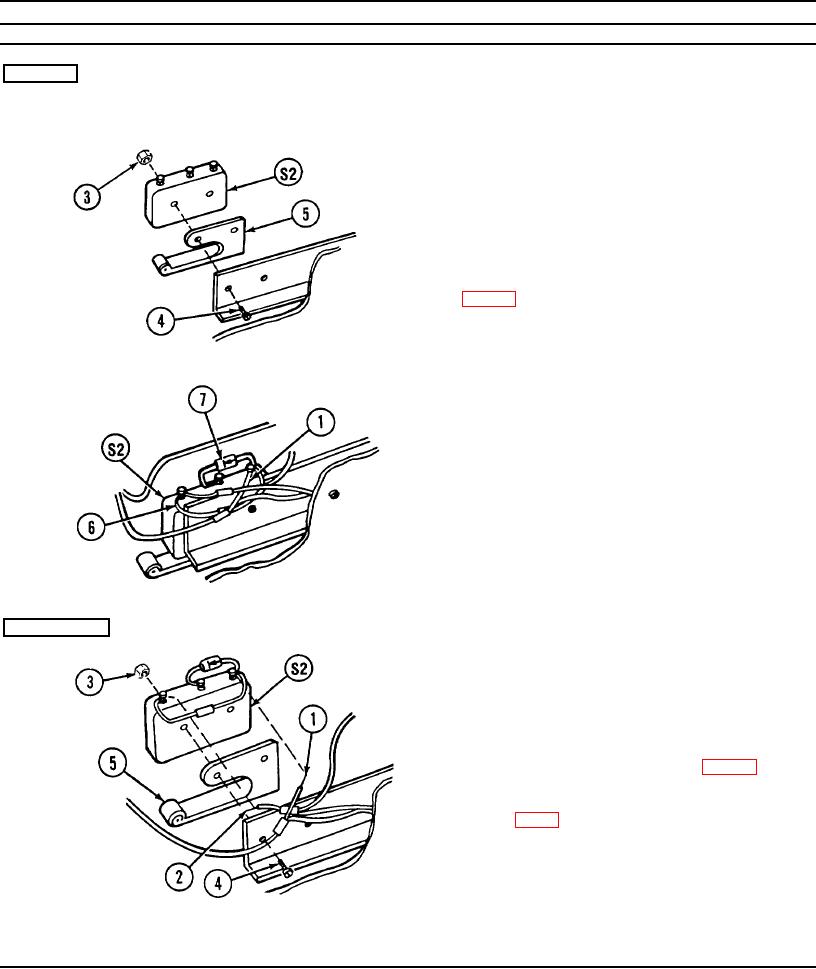
REMOVAL
Airflow Valve
S2 sensitive switch and
1.
Tag and unsolder wire (1) from normally
adapter
closed (NC) terminal on S2 sensitive switch.
2.
Tag and unsolder wire (2) from common (C)
terminal on S2 sensitive switch.
3.
Remove two nuts (3) and screws (4).
4.
Remove S2 sensitive switch and adapter (5).
5.
Remove and retain capacitor (6) and diode (7)
INSTALLATION
1.
Install S2 sensitive switch and adapter (5) using
two screws (4) and nuts (3).
2.
Solder wire (1) to normally closed (NC)
terminal of S2 sensitive switch.
3.
Reinstall diode (7) and capacitor (6) (p. 2-17).
4.
Coat electrical connections with oil varnish
(item 3, app C).
2-18