
TM 3-4240-302-30&P-6
LOCATION
ITEM
ACTION
REMOVAL
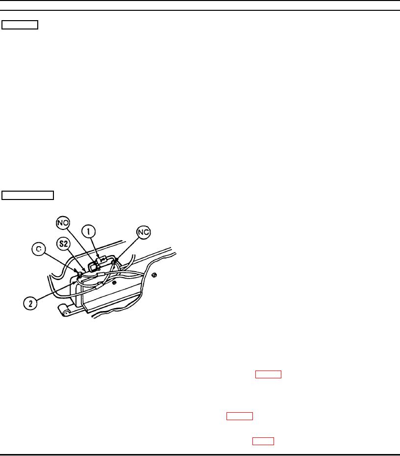
Airflow Valve
Diode and capacitor on
CAUTION
S2 sensitive switch
Apply heat sink pliers to leads of diode when
unsoldering. Excessive heat will damage the
diode.
1.
Unsolder diode (1) from normally closed (NC)
and from normally open (NO) terminals on S2
sensitive switch.
2.
Unsolder capacitor (2) from normally closed
(NC) terminal and from common (C) terminal
on S2 sensitive switch.
INSTALLATION
1.
Cut and bend leads of diode (1) and capacitor
(2) using the old parts as a pattern.
CAUTION
Apply heat sink pliers to leads of diode when
soldering. Excessive heat will damage the
diode.
CAUTION
Diode must be connected properly or
damage will result. Obse rve the banded end
of the diode.
2.
Solder diode (1) leads to normally closed (NC)
terminal and to normally open (NO) terminal
on S2 sensitive switch. Ensure that banded end
is installed on NO terminal. Refer to wiring
diagram (p. 2-19).
3.
Solder capacitor (2) leads to normally closed
(NC) terminal and to common (C) terminal on
S2 sensitive switch. Refer to wiring diagram
4.
Coat electrical connections with oil varnish
(item 3, app C).
2-17