TM 9-6230-210-13&P
LEGEND
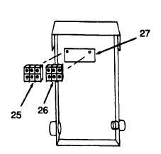
25 TERMINAL
SECTION
26 TERMINAL
SECTION
27 MOUNTING
PLATE
NOTE
Terminal sections snap out from plate.
n. Remove terminal sections (25 and 26) from mounting plate (27).
o. Use hammer to straighter dents in the control panel.
p. Weld cracks and spot paint as necessary.
q. If control panel is determined to be unserviceable, replace it with a serviceable item from stock.
r. Install toggle switch (para 4.21).
s. Install battery charger (para 4.32).
t. Snap terminal sections (25 and 26) into place on mounting plate (27).
u. Install installation plate (24) and terminal strip (23) and secure with two assembled screws (22).
v. Position insulation plate (21) and mounting plate (20) in place and secure with two assembled screws (1 9).
w. Install three screws (16) through splash panel.
x. Install three spacers (18).
y. Install control panel (17).
z. Install ground lug on bottom screw. (Not called out on illustration).
aa. Install three screws (16), lockwashers (15), and nuts (14) and tighten.
ab. Install circuit breakers (para 4.21).
ac. Install duplex receptacle (4.17).
ad. Insert cable (12) through connector (13) and tighten collar (11).
5-7