TM 9-4940-568-34
2-27
Table 2-7. Crane Troubleshooting (CONT).
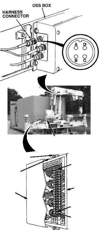
(1) Check disconnected harness
connector for continuity between
terminals B and A.
(a)
If continuity is present, replace
harness (TM 9-4940-568-20).
(b)
If continuity is not present, go
to Step (2) below.
(2) Check disconnected harness
connector for continuity between
terminals B and D.
(a)
If continuity is present,
replace harness
(TM 9-4940-568-20).
(b)
If continuity is not present, go
to Step (3) below.
(3) Connect harness connector to OSS
box.
(4) Set multimeter to volts dc.
(5) Connect multimeter negative lead
to known good ground.
(6) Connect multimeter positive lead
to one of the four white wires
disconnected from terminal 18 with
ENGINE switch OFF
(TM 9-4940-568-10).
(7) Turn ON FRS.
(8) Set crane main POWER switch to
ON position.
(9) Repeat Steps (6) through (8) until
wire with 22 to 28 vdc present is
found. Repair white wire (Fig 2-1)
with 22 to 28 vdc present or replace
harness after completing
Steps (10) through (11) below.
(10) Set crane main power switch to OFF
position.
(11) Turn OFF FRS.
CONTINUITY TEST
Remove all jewelry such as rings, dog tags, bracelets, etc. If jewelry or tools contact positive electrical
circuits a direct short may result. Damage to equipment, injury or death to personnel may result.
Disconnected white wires should not be in
contact.
Steps (4) through (11) are for crane junction
box.
White wires should have 0 vdc present when
OSS is not activated. Faulty wire is shorted
to a wire with 22 to 28 vdc present.
NOTE
SCREW
TERMINAL 18
TERMINAL 19
TERMINAL 1
COVER
CLIP
JUNCTION
BOX
CRANE POWER
SWITCH