TM 9-4940-568-34
5-130
5-22. GENERATOR TESTING (CONT).
c.
Testing Exciter Rectifier Bridge (Rotating Rectifier Assembly).
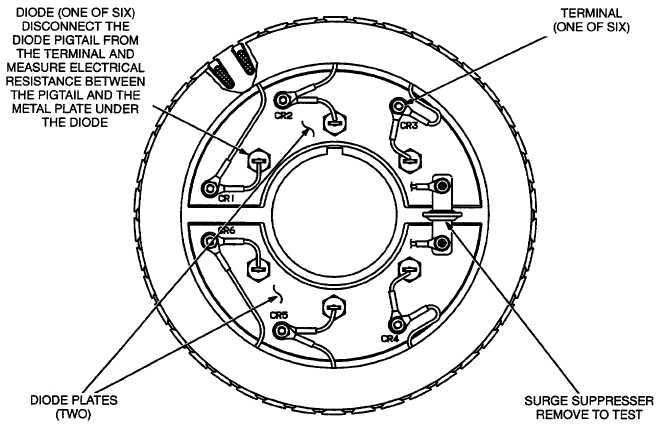
The exciter rectifier bridge is mounted on the exciter rotor, inboard, facing the main rotor. It consists of a positive
plate and a negative plate, split diametrically. Each carries three diodes, three terminal posts for connecting exciter
rotor leads to the diode pigtails and a terminal for the main rotor (generator field) lead. A surge suppressor is
connected across the two plates to prevent transient voltages that could damage the diodes.
(1)
Testing the Diodes: Disconnect the diode pigtails from the terminal posts. Using an ohmmeter, measure
electrical resistance between each diode pigtail and the plate on which the diode is mounted. Reverse the
meter test probes and repeat the tests. The electrical resistance across each diode should be high in one
direction and low in the other. If the resistance is high or low in both directions, replace the diode.
(2)
Replacing Diodes: Make sure the replacement diode is of the correct polarity. Disconnect the pigtail
from the terminal post and unscrew the old diode. Apply heat-shrink compound under the head of the
diode. Make sure the compound does not get on the threads. Tighten the diodes to 36 to 42 lb-in (4 to
4.8 N.m) and the pigtail terminals to 24 lb-in (2.7 N.m) when reassembling.
Layers of dust can cause diodes to overheat and fail. Brush dust off regularly.
(3)
Surge Suppressor Testing and Replacement: Remove the suppressor. Replace the suppressor if it appears
to have overheated or if ohmmeter readings indicate less than infinite resistance (end of scale) in both
directions. Tighten the terminals to 24 lb-in (2.7 N.m) when reassembling.