10
1
5
4
7
2
3
8
6
1
7
9
TM 9-4940-568-20
4-27
This task covers:
a. Removal
b. Installation
c. Follow-On Maintenance
INITIAL SETUP
Equipment Condition
FRS unloaded, (TM 9-4940-568-10)
Shelter stowage rack removed, (Para 4-9)
Brush guard support arms removed, (Para 4-8)
Hydraulic reservoir removed, (Para 4-3)
Tools and Special Tools
Tool Kit, General Mechanic’s: Automotive
(Item 30, Appendix G)
Lifting Device, Minimum Capacity 500 lbs
(227 kg)
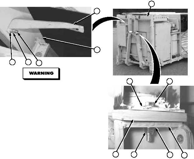
4-7. BRUSH GUARD REPLACEMENT.
Materials/Parts
Tags, Identification (Item 40, Appendix C)
Locknut (Item 55, Appendix F)
Locknut (2) (Item 38, Appendix F)
Personnel Required
Two
Materials/Parts
Locknut (4) (Item 50, Appendix F)
a.
Removal.
Brush guard weighs 444 lbs (201 kg).
Attach suitable lifting device for
removal and properly support brush
guard to prevent any injury to personnel.
(1)
With the aid of an assistant, attach suitable
lifting device to brush guard assembly (1).
(2)
Remove locknut (2), two washers (3), screw
(4) and angle support bracket (5) from brush
guard assembly (1).
NOTE
Note quantity of shims prior to removal.
(3)
Remove two locknuts (6), four washers (7),
two screws (8) and shims (9) from bail hook
post (10). Discard locknuts.