TM 9-2330-238-14
5-11. LANDING GEAR MAINTENANCE
(EARLY MODEL) (Con’t).
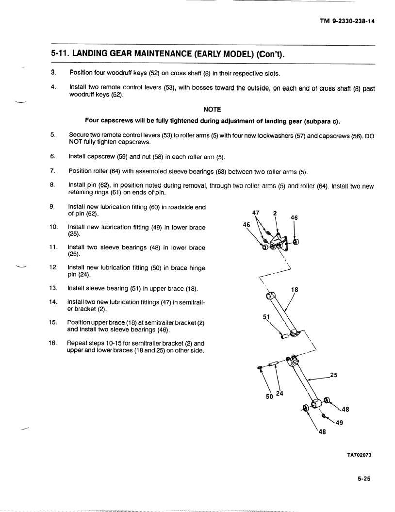
3.
4.
5.
6.
7.
8.
9.
10.
11.
13.
14.
15.
16.
Position four woodruff
keys (52) on cross shaft (8) in their respective
slots.
Install two remote control
levers (53), with bosses
toward the outside,
on each end of cross shaft (8) past
woodruff
keys (52).
NOTE
Four capscrews
will be fully tightened
during adjustment
of landing gear (subpara c).
Secure two remote control levers (53) to roller arms (5) with four new Iockwashers
(57) and capscrews
(56). DO
NOT fully tighten capscrews.
Install capscrew
(59) and nut (58) in each roller arm (5).
Position roller (64) with assembled
sleeve bearings
(63) between two roller arms (5).
Install pin (62), in position
noted during removal, through two roller arms (5) and roller (64). Install two new
retaining
rings (61) on ends of pin.
Install new lubrication
fitting (60) in roadside
end
of pin (62).
Install new lubrication
fitting
(49) in lower brace
(25).
Install two sleeve
bearings
(48) in lower brace
(25).
Install new lubrication
fitting
(50) in brace hinge
pin (24).
Install sleeve bearing
(51) in upper brace (18).
Install two new lubrication
fittings (47) in semitrail-
er bracket (2).
Position upper brace (18) at semitrailer bracket (2)
and install two sleeve bearings
(46).
Repeat steps 10-15 for semitrailer bracket (2) and
upper and lower braces (18 and 25) on other side.
TA702073
5-25