3-05
Fuel System
3-05
expel one pint. Close the restrictor One pint or more of fuel
Capacity (Volume) Test
should be expelled within the specified time limit
With the fuel pump pressure within specifications. Test the
If the pump volume is below specifications, repeat the test using
capacity (volume) as follows:
an auxiliary fuel supply and a new fuel filter. If the pump volume
I.
Operate the engine at the specified idle rpm.
meets specifications while using the auxiliary fuel supply. Check for a
2.
Open the hose restrictor and expel the fuel into the container
restriction in the fuel supply from the tank and for the tank not venting
(Figure 3), while observing the time required to
properly
REMOVAL AND INSTALLATION
FUEL PUMP ASSEMBLY
Removal
2.
Position the new gasket on the pump in position against the
1.
Disconnect the inlet and outlet lines at the fuel pump.
mounting pad Make sure the rocker arm is riding on the
2.
Remove the pump attaching screws, then remove the pump and
camshaft eccentric (Turn the engine over until the fuel pump
the gasket Discard the gasket.
eccentric is on the low side of the stroke.)
3.
Press the pump tight against the pad. install the attaching
screws and alternately torque them to specifications
Installation
4.
Connect the fuel inlet and outlet lines.
1.
Remove all the gasket material from the mounting pad and
5.
()perate the engine and check for leaks
pump flange. Apply oil-resistant sealer to both sides of a new
gasket and to the threads on the attaching bolts.
HOLLEY 1940 ONE-BARREL
CARBURETOR
DESCRIPTION AND OPERATION
The Holley 1940 one-barrel carburetor used on the 300 CID
engines includes four basic fuel metering systems. The idle system
provides a reasonable rich mixture for smooth idle and a transfer
system that operates during low speeds The main metering system
provides the most economical mixture for normal cruising conditions
The accelerator pump system mechanically provides additional fuel
during acceleration. The power enrichment s stem provides a richer
mixture when high power output is desired In addition to these four
basic systems, there is a fuel inlet system that constantly supplies the
fuel to the metering system.
The choke system supplies a rich mixture to start the engine
when cold and a slightly richer than normal mixture for cold engine
operation The 1940 carburetor is equipped with a hand choke located
on the dash.
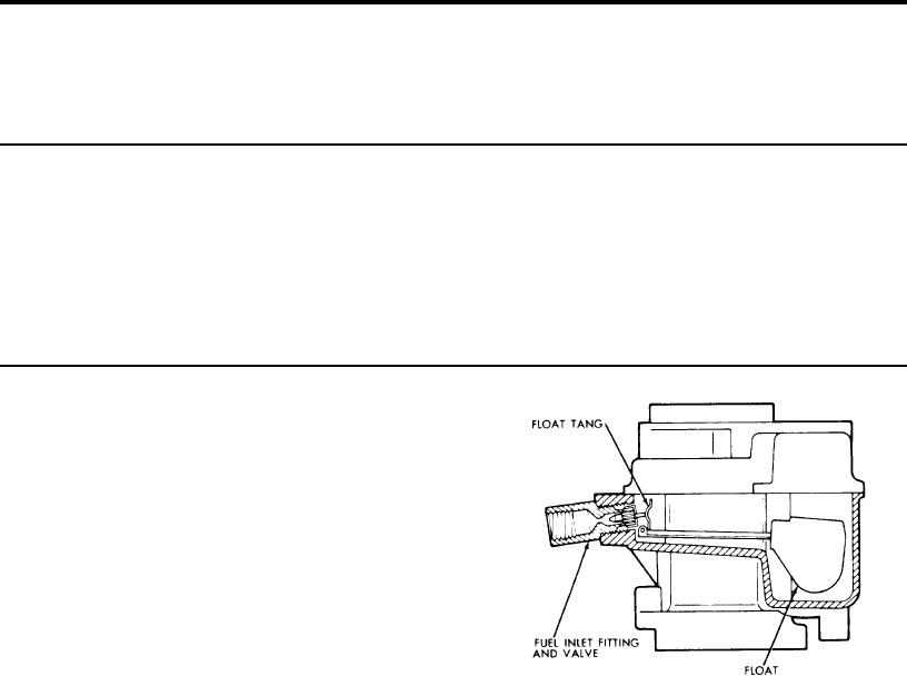
FIG. 4. Fuel Inlet System, Model 1940
FUEL INLET SYSTEM (FIG. 4)
All fuel enters the fuel bowl through the fuel inlet fitting in the
IDLE SYSTEM (FIG. 5)
carburetor body. The 'viton" tipped fuel inlet needle seats directly in
Fuel used during curb and low speed operation flows through
the fuel inlet fitting. The needle is retained by a cap that permits the
the main jet into the main well.
fuel to flow out of holes in the side of the cap. The design of the fuel
An angular connecting idle well intersects the main well. An idle
bowl eliminates the need for a fuel baffle. The fuel inlet needle is
tube Is installed in the idle well. Fuel travels into the idle well and
controlled by a dual lung nitrophyl (a closed cellular buoyant material
through the restriction into the idle tube. This metered fuel mixes with
which cannot collapse or leak) float and a stainless steel float lever
air which enters through the idle air bleed located in the fuel bowl
which is hinged by a stainless steel float shaft.
cover.
The fuel inlet system must constantly maintain the specified
At curb idle the air and fuel mixture flows down the idle channel
level of fuel as the basic fuel metering systems are calibrated to
and is further mixed or broken up by air entering the Idle channel
deliver the proper mixture only when the fuel is at this level. When the
through the transfer slot which is above the throttle valve at curb idle.
fuel level in the bowl drops, the float also drops permitting additional
During low speed operation the throttle valve moves, exposing
fuel to flow past the fuel inlet needle into the bowl.
the transfer slot to manifold vacuum and fuel begins to flow through
The float chamber is vented internally into the air horn. At idle
the transfer slot as well as the idle port. As the throttle valve is opened
speed the float may be vented externally to the fuel canister.
further .d engine speed increases. the air flow through the carburetor
also increases.
This increased air flow creates a vacuum or
depression in the venturi and booster nozzle and the main metering
system begins to discharge air and fuel.

