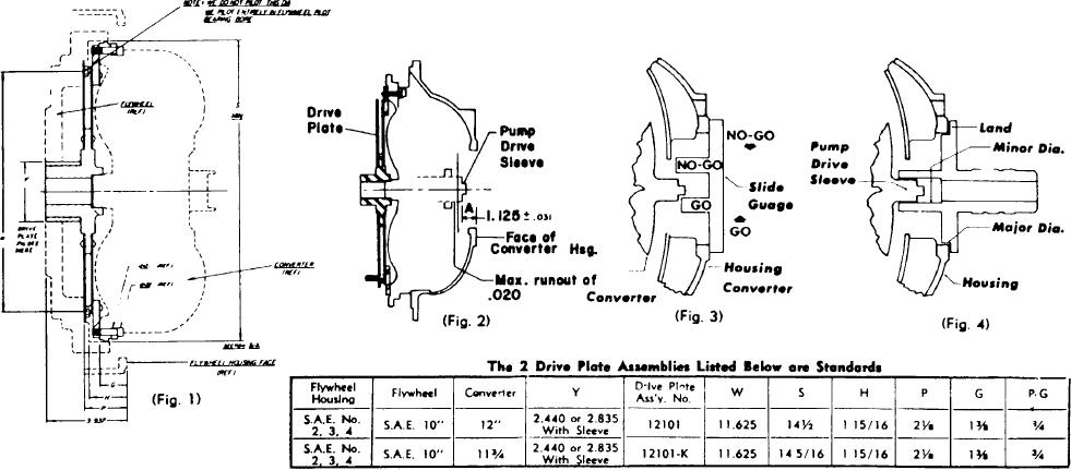
TORQUE CONVERTER INSTALLATION DATA
4. Remove the converter housing from the Revers-O-Matic and attach
1. Preliminary checks should be made for the dimensions shown In Fig
this to the engine flywheel housing The capscrews and lockwashers
No. 1, also the following must be within SAE tolerances before
for this are not ordinarily supplied
starting converter Installation
5. The location of the pump drive end of the torque converter (shown
A. Engine flywheel face runout.
cs dimension "A" Fig #2) must be checked on all installations Due to
B. Engine flywheel housing pilot bore runout, and parallelism of
the flexibility of the drive plate allowing the converter to tilt slightly, it
mounting face in relation to flywheel.
will be necessary to hold the converter hub In the center position
2. Attach the converter drive plate assembly to the engine flywheel
6. The dimension "A" Is to be 1/8" plus or minus 1/32" and may be
with the #F10030-12 capscrew (3/8 x 3/4) and the #F16202
checked with a depth mike, a closely graduated scale rule and a
lockwasher supplied with the assembly. If the drive hub sleeve is
straight edge, or the #CDG-1 "Go" and "No-Go" gauge (see Fig -3)
required, it should be installed at this time.
is available for this check The dimension "A" Is to be checked at the
3. Attach the torque converter to the converter drive plate with the #F1
end of the pump drive sleeve and not at the ends of the two driving
1004-20NY socket head capscrew (5/16 x 1 1/4) and the #4012121
lugs. (see Fig. #2)
half round washer supplied with the assembly. Be sure the
converter is positioned so that the drain plugs #45015 on the front
side of the converter do not interfere with the drive plate.
B-6

