
TM 5-3805-296-23-6
0429
INSTALLATION CONTINUED
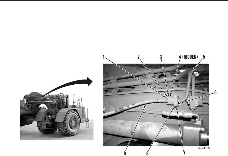
7. Install new O-ring (Figure 14, Item 4) on hydraulic hose (Figure 14, Item 9).
8. Install hydraulic hose (Figure 14, Item 9), two flange halves (Figure 14, Item 3), four washers
(Figure 14, Item 2), and bolts (Figure 14, Item 1) on hydraulic line (Figure 14, Item 5).
9. Install hydraulic line (Figure 14, Item 5), clamp (Figure 14, Item 8), two washers (Figure 14, Item 7), and bolts
(Figure 14, Item 6) on machine.
Figure 14. Crossover Line, Right.
0429
END OF TASK