
TM 5-3805-296-23-6
0417
BOWL CYLINDER HOSES AND LINES INSTALLATION CONTINUED
NOTE
This procedure is for right bowl cylinder hoses. Follow same steps for left bowl cylinder
hoses.
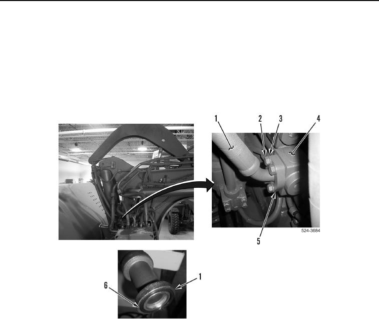
39. Install new O-ring (Figure 47, Item 6) on hydraulic hose (Figure 47, Item 1).
40. Install hydraulic hose (Figure 47, Item 1), two flange halves (Figure 47, Item 5), four washers
(Figure 47, Item 3), and bolts (Figure 47, Item 2) on hydraulic line (Figure 47, Item 4).
Figure 47. Right Cylinder Up Line Connection.
0417