
TM 5-3805-296-23-6
0405
ASSEMBLY CONTINUED
NOTE
Install coil as noted during removal.
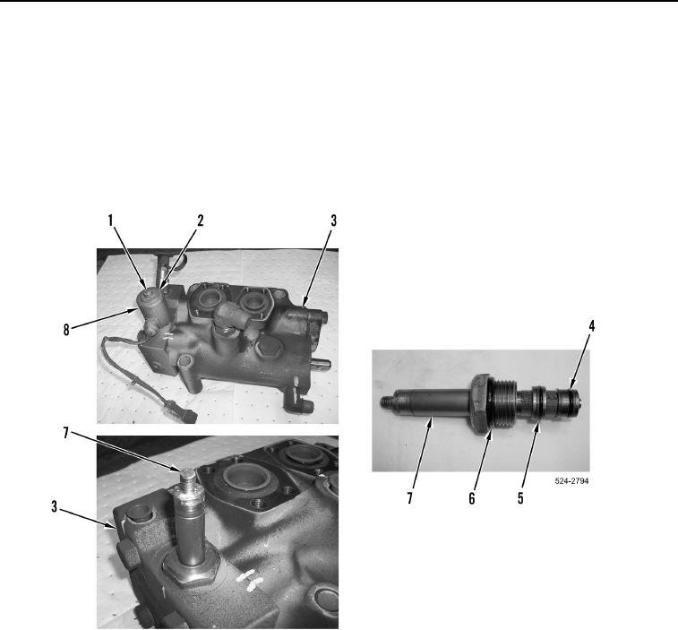
6. Install three new O-rings (Figure 16, Items 4, 5, and 6) on plunger (Figure 16, Item 7).
7. Install plunger (Figure 16, Item 7) on leveling valve (Figure 16, Item 3).
8. Install coil (Figure 16, Item 8), washer (Figure 16, Item 2), and nut (Figure 16, Item 1) on leveling valve
(Figure 16, Item 3).
Figure 16. Solenoid.
0405
END OF TASK