
TM 5-3805-296-23-6
0396
INSTALLATION
000396
NOTE
Remove plugs and caps from hydraulic hoses and fittings.
Install hydraulic hoses as tagged during removal.
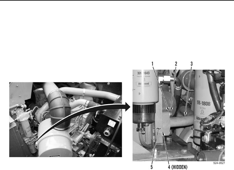
1. Install pipe (Figure 3, Item 3) and new seal (Figure 3, Item 4) on hydraulic tank (Figure 3, Item 5) and
machine with four bolts (Figure 3, Item 2) and washers (Figure 3, Item 1).
Figure 3. Pipe.
0396
2. Position hydraulic hose (Figure 4, Item 6) on machine.
3. Install new O-ring (Figure 4, Item 8) on hydraulic hose (Figure 4, Item 6).
4. Install hydraulic hose (Figure 4, Item 6), two flange halves (Figure 4, Item 9), four washers (Figure 4, Item 10),
and bolts (Figure 4, Item 11) on secondary steering gear pump (Figure 4, Item 7).
5. Install new O-ring (Figure 4, Item 4) on hydraulic hose (Figure 4, Item 6).
6. Install hydraulic hose (Figure 4, Item 6), two flange halves (Figure 4, Item 5), four washers (Figure 4, Item 2),
and bolts (Figure 4, Item 1) on hydraulic line (Figure 4, Item 3).