
TM 5-3805-296-23-5
0371
REMOVAL
000371
NOTE
The procedure for left and right rear tire wheel assembly removal and installation is
identical. Left rear tire wheel assembly is shown in this procedure.
1. Start engine and release brakes (TM 5-3805-296-10).
2. Stop engine (TM 5-3805-296-10).
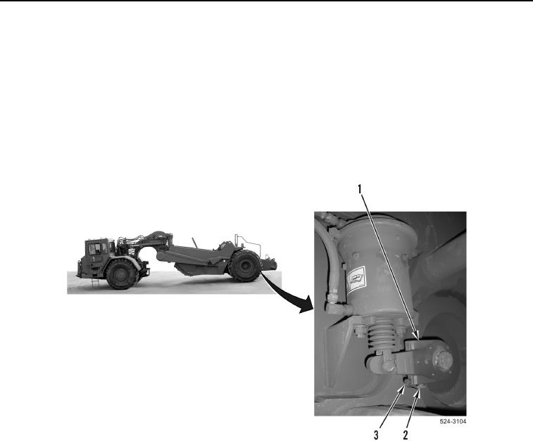
3. Loosen bolt (Figure 1, Item 3) on slack adjuster (Figure 1, Item 1) three full turns.
4. Loosen slack adjust bolt (Figure 1, Item 2) on slack adjustor (Figure 1, Item 1) until bolt does not turn.
Figure 1. Slack Adjuster.
0371