
TM 5-3805-296-23-5
0367
BRAKE DRUM INSTALLATION CONTINUED
NOTE
Install bolts in bolt holes from alignment pins removed in previous step.
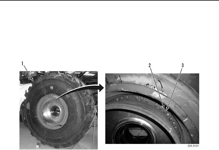
5. Install two new bolts (Figure 14, Item 3) and spacers (Figure 14, Item 2) on wheel assembly
(Figure 14, Item 1).
6. Tighten 42 bolts (Figure 14, Item 3) to 74 lb-ft (100 Nm). Tighten bolts an additional 120 degrees.
Figure 14. Bolts.
0367
END OF TASK